
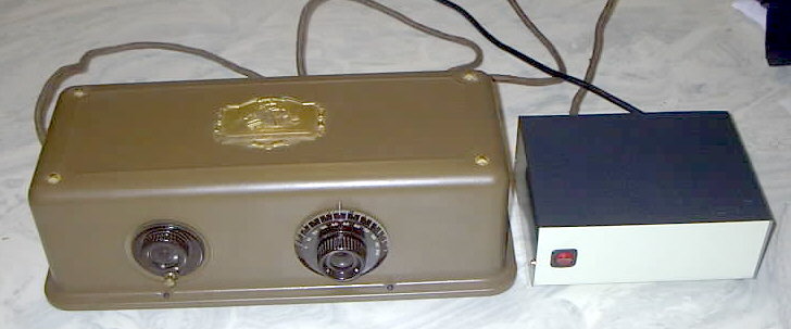
Shown is an Atwater Kent Model 20 Compact (Type No. 7570) and matching Atwater Kent model H horn-type speaker.
(Since it is impossible to make a cat pose for a picture, I'll try again to get a better one... some day...)
|
Note: Presumably, you have read the related page -
the page about Restoring my Atwater Kent
Model 20 Compact. If you haven't yet read
that page, please be sure to do so. Also, take a look at my
Atwater Kent Model 20C gallery.
Notice: The power supply described produces hazardous (and potentially lethal) voltages. Extreme care should be taken when handling such voltages. Observe proper high-voltage handling precautions. If you aren't familiar with such precautions, please become educated with them prior to working with dangerous voltages.
It is recommended that this schematic be printed in landscape mode. (Updated to version 1.2 of the schematic as of 11/2000.)
A Bit of Background:
This power supply is intended to operate the Atwater Kent Model 20 Compact receiver. Like many receivers of its era (e.g. the mid 1920's) this is a battery-operated receiver. In that era, the technology to build an AC operated power supply for the then-available vacuum tubes existed, but implementation was rather expensive. Furthermore, there were a lot of people who still did not have electrical power - or, at least, a reliable source of it.
The obvious alternative to an AC-operated power supply is battery power. Not including the source of power with the cost of the radio greatly reduced its price. Furthermore, batteries that could be used for operating the receiver were readily available in the form of vehicle and dry cell batteries. With the proper care, many hours of listening could be provided by a set of batteries before they required replacement and/or charging.
Why are there so many voltages required?
With a string of batteries it is relatively easy to provide "taps" for various voltages to operate different circuits of the receiver. Providing these different taps also provides a means of isolating the various sections of the receiver. Let's take the Atwater Kent Model 20C (type 7570) as an example:
 |
This radio requires +90, +67.5, +22.5 and -4.5 volts for the various stages:
The RF stages require +67.5 volts. These tubes are operated at zero bias and the lower plate voltage prevents these stages from being driven to the extent that they would be were they operated at 90 volts.
The Detector stage requires 22.5 volts. This stage is a grid leak detector, and it would tend to operate with the highest idling current of all of the tubes were it operated at the higher voltage of another stage. This detector stage is also the most sensitive to power supply variations and by operating it from the 22.5 volt tap, it is "closest" to the common point on the battery and has the lowest impedance to "ground."
The filament supply was typically provided by a 6 volt lead acid (car-type) battery: When fully charged, this battery would provide well over 6 volts, dropping down to below 5 volts as it was depleted. A pair of rheostats on the front of the radio provided a means of adjusting the filament voltage over the course of the battery life.
Because the tubes have filaments rated at 5 volts, it was decided to provide precisely that voltage. This also means that when the rheostats are turned fully clockwise, no more than the rated filament voltage can be applied to the (rather expensive and fragile) tubes.
Connecting the power supply
to the AK-20C:
Because this power supply could be adapted to a number of
different radios (it, in fact, has!) the diagram doesn't show the
wiring connections specific to the AK-20C. Below, however,
that information is included:
|
The Filament Supply:
The power supply consists of a pair of 12.6 volt, 1.5 amp center-tapped filament transformers (T1 and T2.) The first of these transformers takes the 120 volt line voltage and drops it down to 12.6 volts AC. A full-wave rectifier consisting of D1 and D2 (using the center-tap) and a pair of 4700 uF filter (C1 and C2) capacitors filter the rectified voltage and apply it to a 7805 5 volt regulator (U1) providing a very clean, ripple-free filament voltage. Note: It would be worth obtaining an LM323 or LM338 for the filament supply, as these regulators are rated for 3 and 5 amps, respectively.
A word of caution, make certain that the version of 7805 you use is rated for at least 1.5 amps: There are TO-3 and TO-220 versions that will current limit at 0.5 amps or 1.0 amps - and those are not useable in this application.) It should be noted that on these radios, the filament voltage must be extremely pure to prevent hum: This is a result of the tubes having directly-heated filaments and their voltage interacting with the cathode-grid ("bias") voltage. If you simply cannot find a 1.5 amp version of a 7805, you can probably get away with two 1 amp 7805's in parallel. More than likely, one of them will take most of the current (because it's voltage is a tiny fraction of a volt higher than the other) but it will simply "pass the buck" to the other 7805 when it can't handle the current. If you want to make it share load equally, then a 0.1 ohm resistor in series with the output of each regulator would help.
A note here: It would have been better if I had found some 15 volt center-tapped (or even 18 volt center-tapped) transformers: The rectified/filtered voltage coming out of T1 is barely adequate to keep the 7805 in regulation. Using the full 12.6 volts and regulating it down to 5 volts would not be advisable as the 1.5 amp transformers may not be able to handle the current drain of the filaments and the high voltage supply - and there would be much more power being dissipated by the regulator, requiring a much larger heat sink! If the voltage regulator gets too hot, it may go into thermal shutdown (causing the voltage to drop as well as hum) and it may have a short operational lifetime.
The Bias Supply:
The two audio amplifier tubes (or just the second tube, in the
case of the 7690) require a -4.5 volt (nominal) bias voltage to
set their operating point. This is obtained by taking a bit
of voltage from T1 and half-wave rectifying it (via D3) to a
negative voltage. This voltage is filtered by C4 and
regulated by U2, a 7905 regulator to provide a clean -5 volt
source. A series diode (D4) provides a 0.6 volt drop,
yielding about -4.4 volts. A 270 ohm resistor (R1) provides
a means for current sinking and the 47 microfarad capacitor (C6)
provides a low-impedance path to ground. It should be noted
that the Atwater Kent manual specifies a voltage between 4.5 and 3
volts as being useable. (Note: Without R1,
rectification of audio on the grid can cause the bias voltage to
go much more negative, putting the tube into cutoff. I
know this, because I'd forgotten to add it at first...)
|
"Ground" is not ground A bit of warning is in order here: The "Common point" of the power supply (i.e. the "zero" voltage point of the filament, plate, and bias supplies) must not be grounded! That is, if you build a power supply do not connect the "zero voltage" point to ground - it must remain floating. Why? A look at the schematic will reveal that the ground antenna terminal is actually connected to one side of the filament supply! If you ground both the zero voltage point and the antenna "ground" terminal, the radio will not work properly and you run the risk of burning out a rheostat! |
The Plate supplies:
The plate voltages are obtained by running 12.6 volts from T1
into the secondary of T2, yielding an isolated
(a factor that is important from both a safety standpoint and
power supply purity) 120 volt AC source. It should be noted
that the preferred transformer would have been one
with an appropriate filament voltage and some
higher-voltage taps for the plate voltages but nowadays, these
transformers are quite difficult to find - but standard 12.6 volt
transformers are quite common.
Remember: If you can find a pair of matched 13-15 VCT transformers - by all means, use them! If they aren't identical, then you will have to adjust the values of one or more of the divider string resistors in the plate supply - or add the zener diode as noted below! Remember that the higher voltage you supply to the 7805, the hotter it will get and the bigger heat sink you'll need!)
The 12.6 volt transformer run "backwards" produces approximately 120 volts AC (line voltage) and the output is half-wave rectified (using rectifier D5 and current-limiting series resistors R2 and R3) and filtered with 100 uf capacitor, C7. The loaded voltage (with the radio connected and operating) at this point is approximately 120 volts. (Note: Owing to the light loading and relatively high filter capacitance, full-wave rectification was not found to be necessary.)
Warm Transformers!:
Please note that when you run a transformer "backwards" like this, it may get a bit warm - even if very lightly loaded - but there shouldn't be any hazard. If this really bothers you, then using a 24 volt transformer with a 240 volt primary as the "step-up" transformer (12 volts into the "24 volt" winding, and getting 120 volts from the "240" volt winding) should run cooler.
Note: There are transformers available with split primaries and secondaries that can be wired in the following manner: The first transformer would be wired with its secondaries and primaries in parallel yielding, say, 120 volts in a 12.6 volts out. The "step up" transformer would be wired with its two primaries and secondaries in series: You'd still get 120 volts AC on the output, but there would be twice as many turns involved and the transformer would run a bit cooler.
Of course, if you happen to have an old "filament/plate" transformer with all of the necessary voltage windings on it - by all means, use it! These are getting harder to find these days. The only thing to remember is that the "common" point on the power supply (the "ground" for all DC voltages) is NOT the same as the radio's antenna ground!
***
The various operating voltages are obtained via a string of
series resistors R4, R6, R7, and R8. The voltage at the
junction of R4 and R6 is approximately 90 volts (loaded)
and this is further filtered with C8. This voltage is fed into the
base of Q1 via R5 - which is used to limit base current.
Next in line, at the junction of R6 and R7, the voltage is about
67.5 volts, and is fed into the base of Q2. Finally, at the
junction of R8 and R9, the voltage is approximately 22.5 volts,
which is fed into the base of Q3.
|
Built as shown in the schematic and operated from 119 volts AC, the unloaded voltages are: 110, 83 and 33 volts for the 90, 67.5 and 22.5 volt sources, respectively. When connected to an on-and-operating Model 20C,
operating at low volume, the voltages are: 87,
65, and 25 volts, respectively - well within the
range of what the radio's tubes can handle. (Actually,
anything from -25% to +10% would operate the radio
pretty well - this isn't a precision piece of
equipment!) Current consumption of the
20C: The current consumption of the Model 20C
from the various supplies is rather modest - but it can
vary widely depending on filament voltage and the
condition of the tubes, not to mention which version of
the 20C that you might have - that is, the 7570 or the
7690.
The conditions below are using a 7570 with a filament voltage supply of 5.0 volts and the two rheostats turned fully-clockwise for maximum filament voltage. No antenna was connected and no signals were tuned in, and a speaker was connected to the terminals. Please note that the currents below could easily vary plus or minus 50%, depending almost entirely on the health of the tubes and the specific supply voltages. Note: I do not own a 7690, so the current consumption shown below is only an estimate.
Remember: When the filaments are turned off (with the "power" switch) there should be ZERO current pulled from the 22.5, 67.5 and 90 volt supplies, so if you see current with the filaments turned off, start looking for a leaky component! Note: If excess current is pulled from only the 90 volt supply verify that your negative bias supply is really functioning! |
Q1, Q2, and Q3 form emitter followers, essentially providing voltage sources approximately equal to the tap voltages. Capacitors at the emitters of Q1, Q2, and Q3 provide bypassing for RF and AF currents. Note the presence of C12 at the emitter of Q3, which provides an extra measure of bypassing.
Q1, Q2 and Q3 may be any NPN transistors capable of handling 200 volts or more. It is recommended that these transistors be in TO-220 packages, or other packages that contain built-in heat sinks. Additionally, U1 (the 7805) should be heat-sinked: It should never run such that it is too hot to touch!.Again, it should be remembered that this circuit does not
regulate the PLATE voltages (unless you added the zener)
but rather it provides a very clean source of DC and the voltages
will vary with the AC line potential. (Refer to the sidebar
for typical unloaded voltages.) This is not to be a cause
for concern as these radios can typically tolerate a 20-30 percent
variation in these operating voltage (these things were designed
to run on batteries, remember?) with little effect on
performance. If you are building a supply for a radio that
requires different voltages, the voltage divider resistors (R4,
R6, R7, and R8) need only be changed appropriately.
Note: If you desire a regulated plate supply voltage, change R4 to 4.7k and put a 1 watt 90 volt zener diode (an NTE-5094A or NTE-5095A will suffice) across C8. (Make sure you do this with the power off!)
Getting parts:
Some of these parts will be available from your local Radio Shack (such as the transformer, capacitors, case, etc.) In the case of the version of the 7805 (or, better yet, the LM323 or LM338 - that will handle the current, you'll have to look around carefully - or just use two in parallel as described above. For some of the "rarer" components - like the high-voltage transistors - you may have to look around.
One possible place for parts is from a defunct PC power supply. Often, these use a pair of high-voltage switching-type NPN transistors on the "primary" side of the switching transformer (look for larger heat-sink mounted transistors that have part numbers beginning with "2SC" near the large input filter capacitors.) Additionally, you can often find some beefy diodes (some of them are dual-diodes in larger-than TO-220 transistor-like packages - and make sure that the diodes are connected in the manner that you need them to be!) that can be used - for the low voltage side of things, at least.
Additionally, you'll usually find some 200+ volt capacitors on the input side - and these work very well in the place of C7, and you'll probably find a 7905 regulator. Be careful of some of the smaller capacitors: Most PC power supplies die due to fan failure and/or one of the smaller capacitors on the TL494 "drying out" and going bad - but that rarely happens to the larger capacitors on the primary side, however...
Of course, as you pull parts off (like the transistors) it would be a good idea to check them to make sure that they aren't bad! To get all of the parts (like the high-voltage transistors) you may need to cannibalize more than one power supply! (If you don't mind it being a bit ugly, you might be able to re-use the power supply case, too!)
Finally...
The entire power supply should be enclosed to prevent accidental contact with high voltages. The connection to the radio was done using a nylon Molex (tm) connector. While this type of connector is definitely not from the radio's era, it provides for a quick, safe, foolproof connection. If you are going to use it as a general-purpose supply for multiple radios it would be advisable to put additional fusing in the power supply (to protect the regulator from an accidental dead short) and the use of the insulated "European-type" barrier strips (the type with no exposed connections - an essential safety factor with the voltages involved) may be more convenient than the molex connectors.
 |
One Man's power supply...
Bill, N2WNS, got an Atwater Kent Model 35 that he wanted to be able to run off AC. The Model 35 is similar to the Model 20 - except that it's tuning capacitors are ganged together (e.g. ONE tuning knob) and it uses SIX tubes (an extra RF amplifier...)
The voltage requirements are the same - but with the one extra tube, the power supply must be expected to supply at least 1.5 amps instead of 1.25. Bill made the following modifications to suit his needs:
 |
Initially, Bill had problems with hum. One of the lessons learned is that it's best to use one regulator capable of the current where possible - rather than trying to parallel two smaller regulators. Another problem had to do with ground loops: With 1.5 amps of filament current floating around, even a short piece of wire can have a few millivolts of voltage drop. Make certain that your filament supply uses "Single-Point Grounding" techniques - that is, all high-current grounds come together at one place - preferably at the negative leads of the filter capacitors. Bill discovered that 50 millivolts of AC ripple across a short ground connection (rather than a true, single-point ground) caused an objectionable amount of hum in the speaker.
After taking care of everything (he rebuilt the power supply, using the same components) he had 2-5 millivolts of hum instead. This level results in an amount of AC noise that is barely audible and isn't objectionable at all.
Remember: These are directly-heated tubes and any hum on the filament supply will be amplified!
For more pictures, go to my Atwater Kent Model 20C gallery.
Go back to the
the AK20 main page.
Go back to KA7OEI's main
site.
Any comments or questions? Send an email!

