Atwater Kent Model 20 Compact picture gallery
(For the 7570)

Several requests have been made to put pictures of the internals of the 20C online - and I've sent the occasional picture or description in email.  Now it's time to actually put pictures of what one looks like on this page.

Keep in mind that this is for the 7570 - and your model may look a bit different.  It is also likely that even for the same model number, slight changes in layout/construction/components were made, so your mileage may vary!


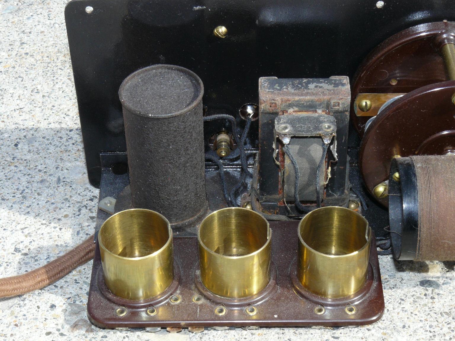
The Model 20C, removed from its case.
Note the brass tube socket collars
typical of the 7570.
First RF stage of the AK20C
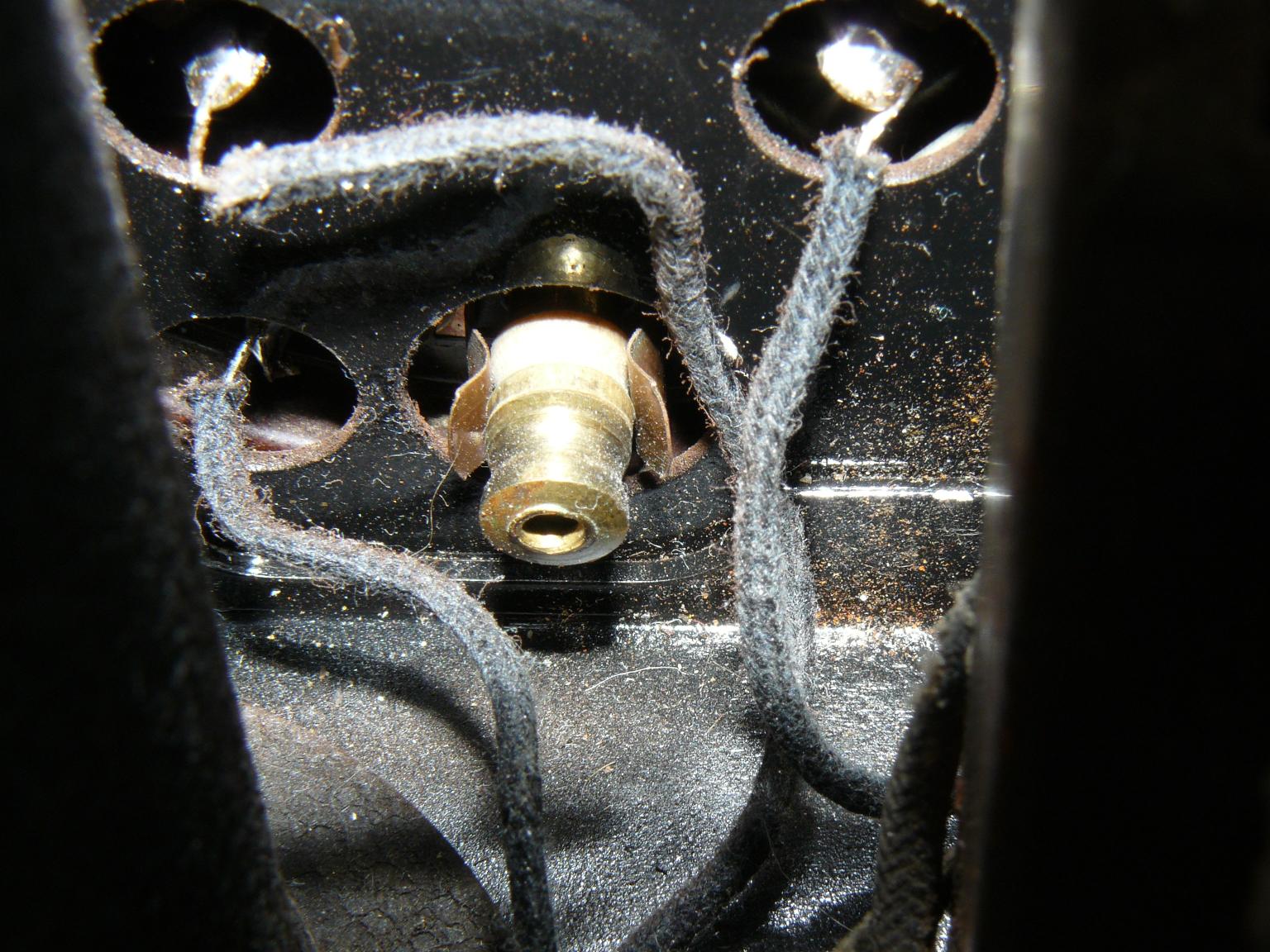
A close-up view of the 1st RF stage.
The antenna connections are
on either side of the tube
socket.
2nd RF stage, viewed from below
The 2nd RF stage (right of center) and the
detector (left edge.)  The 250 pf
capacitor is under the coil, on the
back of the tuning capacitor.
Top view of the 1st and 2nd RF stages.
Right-to-left, the detector, 1st and
2nd RF stages.
Underneath the 2nd and 1st RF stages
Underneath the 1st and 2nd RF
stages.  Note the 600 ohms wire-
wound resistors on the back of
the tuning capacitors.
Top view of the detector and AF stages
Top view of the AF and detector stages.
Underneath the AF and detector stages
Underneath the Detector and AF
stages.  The white cylinder on the
right edge is the "2-4 Meg" grid-leak
resistor.  The 0.002 uf capacitor is
to the left of this resistor.
Top view of 2nd RF socket and 0.3uF bypass capacitor
A top view looking down upon the
2nd RF tube socket.  The 0.3uf bypass
capacitor is the gray box in front of the
socket, between the 2nd and 3rd stage
tuning capacitors.
Close-up view of the antenna tap switch
A closeup of the "Antenna Tap"
switch.
View of top of AF section showing audio transformers and power switch
A view from above the AF/Detector
strip showing the audio transformers
and the power switch.  The open-frame
transformer (which was on the radio
when I got it) is a vintage replacement:
It's a "DeForest" brand!
Close-up view of the power switch
Close-up view of the power switch.

Close-up view of the 600 ohm resistor on the back of the 2nd tuning capacitor
Close-up view of the 600ohm resistor on the
back of the 2nd tuning capacitor

Click on any picture to get a larger version.


A few comments:

If you think that there should be a picture of something on this radio that isn't shown, please let me know.  (Yes, I know that the front isn't shown above, but you probably already know what it looks like if you are here.)

Click here for a redrawn schematic of this radio.


A few other Atwater-Kent and "vintage radio" related links:

Jim's Antique Radio Page has information on several radios, including technical information and owner's manuals covering the Model 20 here.

Note:  The links on Jim's page have been unreliable as of late - here are a few alternates (you may have to right-click on the link to properly download the file(s):

The Sky Waves web site - with info on listening with the "vintage" radios, including the Model 20.

Other links:

An AC-Operated power supply for the Atwater Kent Model 20 Compact Receiver.

Go back to the the AK20 main page.

Go back to KA7OEI's main site.

Any comments or questions?  Send an email!

This page copyright 2001-2008 and is maintained by Clint Turner, KA7OEI.  It was last updated on 20080227