 |
For a similar page about the FEI FE-5680A rubidium reference, click here.
Note: Unlike the FE-5680A Rubidium, the Efratom LPRO-101 is directly suitable for providing a 10 MHz reference for microwave transverters - see below for more info.
Why a frequency reference?
When operating on the microwave amateur radio bands, narrowband modes (such as SSB or CW) are often used to maximize the link margin - that is, be able to talk when signals are weak as the SSB or CW modes can offer 10's of dB improvement over the wide FM modes used with Gunn transceivers.
There is a catch, however: The use of microwave frequencies and narrowband modes such as SSB or CW means that the one must maintain pretty good frequency stability and accuracy:
- Stability is important as a drift of even a few hundred Hz at the operating frequency (in the GHz range!) can affect intelligibility of voice - or, if CW is being used for weak-signal work, such drifting can move the received signal outside the receiver's passband filter! Having to "chase" the frequency around is not only distracting, but it complicates being able to communicate in the first place.
- Accuracy is also critical because it is important that
both parties be confident that their stated operating
frequencies are reasonably close to where they think they
are, frequency-wise. If a contact is arranged
beforehand, it is vital that both parties be able to find
each other simply by knowing the intended frequency of
communication and as long as the two parties are within
several hundred Hz of each other, it is more likely that
they will be able to complete the contact. If the
error was on the order of several kHz or 10's of kHz,
"hunting" would be required to find the signal and if those
signals are weak, they might be missed entirely -
particularly if, in addition to tuning around, it was also
necessary to move the antennas about as well!
- Only one reference is required. It's better
to expend the effort in putting together one "master",
stable reference rather than each piece of gear having its
own reference. In this way, the extra money, time and
effort saved can be put toward having this one reference be
as good as you can make it.
- Power savings. Having one common reference can also be convenient if one is operating portable using battery power. Using an external reference means that one doesn't need to keep all of those individual pieces of gear "warmed up" all of the time to maintain stability, turning it on (and draining battery power) only when it is needed. For this reason, many amateur radio operators (and commercial equipment manufacturers, for that matter) design their gear to accept a 10 MHz input from a known-accurate and stable source.
About this frequency reference:
The Rubidium frequency reference - an Efratom LPRO-101 - was obtained on the surplus market (e.g. EvilBay), having (probably) been pulled from obsolete cellular telephone gear. Where crystal-based oscillators use the mechanical properties of the quartz to determine the operating frequency, a Rubidium reference utilizes an atomic resonance based on the passage of light passing through a Rubidium-vapor lamp in an RF field. This mechanism of operation is fundamentally more stable than that of a quartz oscillator, allowing orders of magnitude greater long-term stability.
Unlike a quartz crystal oscillator which has no clearly-defined "wear out" period and, if well-designed, can actually improve as time goes on, a Rubidium reference has a definite lifetime associated with its lamp: As the unit operates, the Rubidium within the lamp is gradually consumed and eventually, too little vapor is available for the atomic resonance to be detected and the unit fails. For this reason, many amateurs that use Rubidium references choose not to leave them on all of the time. For "base station" use, a GPS-based disciplined quartz oscillator is often used as the "primary" reference against which the Rubidium unit is compared. Since a GPS-based disciplined reference is, by its nature, not "portable" (that is, you can't just move it around unless you stay in one location for many hours, giving it time to re-lock) a Rubidium reference fills the niche providing very high accuracy and stability in a portable package..
At room temperature (around 68F/25C) the LPRO-101 takes 3-5 minutes to warm up and "lock" (much faster than a crystal-oven reference!) immediately providing accuracy equal or better than a good-quality "ovenized" quartz oscillator, gradually achieving something approaching its ultimate accuracy after a few 10's of minutes. The LPRO-101 has two "frequency trim" adjustments - one "mechanical" via a potentiometer and the other "electrical" (from its connector) - that can be used to provide fine-tuning of its output frequency. Generally speaking, one would set the Rubidium's frequency just once using the potentometer using as close to a "primary" reference as you can find (such as a GPS disciplined oscillator for most of us!) as a basis of comparison while the electrical adjustment (on one of the pins of the connector) would be used if one were to incorporate the reference into, say, a GPS disciplined system or were to add a means of temperature compensation to further-increase accuracy.
The LPRO-101 has a number of other outputs as well. In addition to the "BITE" (which stands for "Built-In Test Equipment") signal (see below) there are several other signals that indicate the unit's internal health - such as the "Lamp Voltage" (which provides a relative indicator of remaining life of the Rubidium lamp) and crystal tuning voltage. While these signals are useful for diagnostic purposes, but I chose not to bring them out of the box with the idea that if the unit were to fail in the field where it might be used, I wouldn't likely be able to do any in-depth diagnosis, anyway! That being said, I may add some "pin jacks" at some point to allow easy checking with a voltmeter.
Comments:
- Once warmed up (after 30 minutes) the lamp voltage on my LPRO-101 is around 7 volts and the crystal tuning voltage is around 6.5 volts - both indicative of still-healthy electronics and physics packages.
- If you don't have something like a GPS Disciplined
oscillator or a cesium reference to which you can calibrate
your newly-acquired rubidium, don't despair: If it
achieves "Physics Lock" it is probably much more
stable and accurate than any quartz-based reference that you
are likely to own even if you can't fine-tune it.
Assembling the unit:
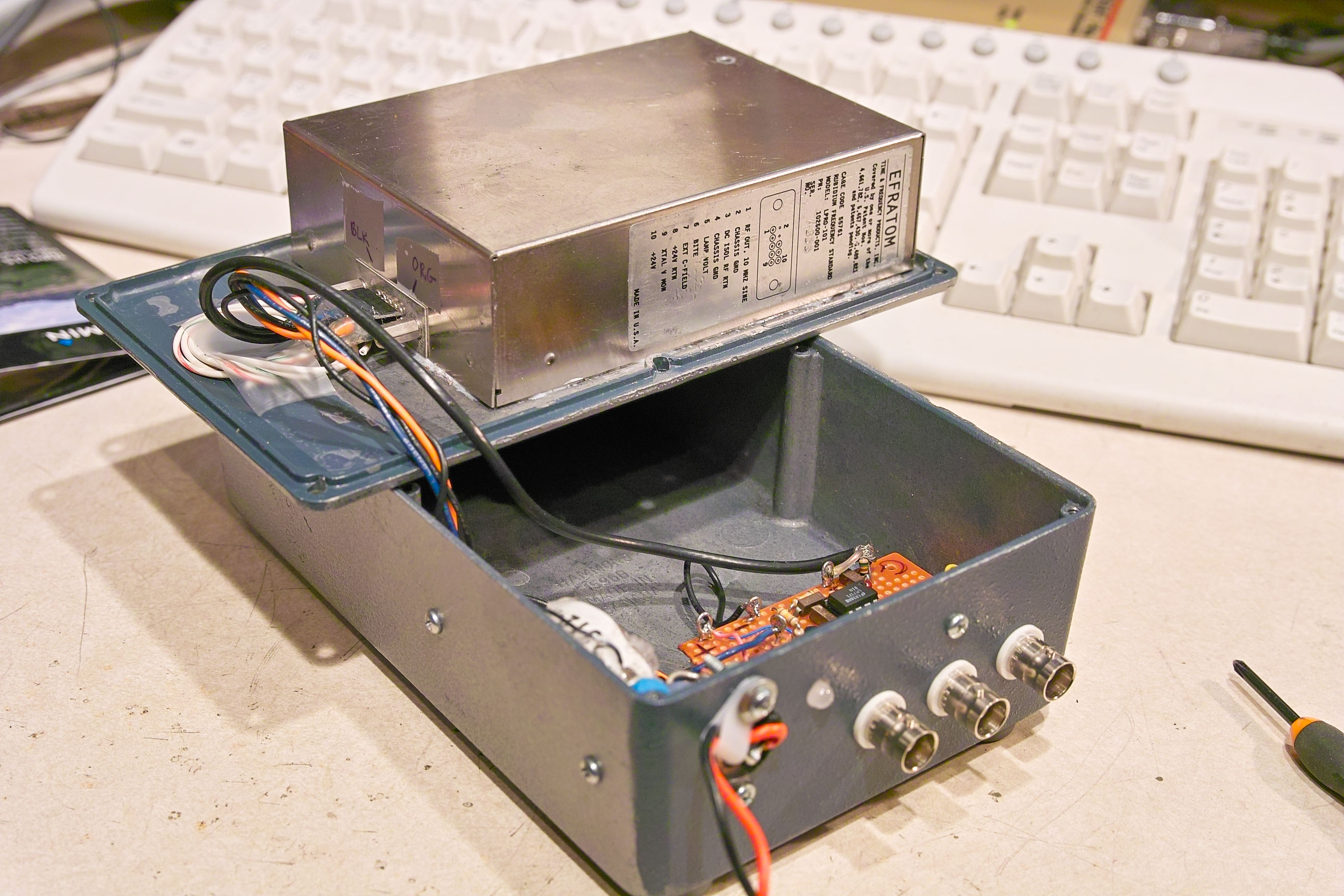
The LPRO-101 unit was originally mounted to a heat sink plate in its originally-configured chassis, but as-shipped from the surplus vendor there was no heat sinking provided for its baseplate. In order to avoid thermally stressing the unit - especially at higher ambient temperatures - it is necessary that it be operated only with a heat sink.
Shown in Figure 1 is the packaged unit, contained in a die-cast aluminum enclosure - a Hammond 1580D series. Mounted to the lid, the aluminum cover alone seems to adequately spread and radiate the heat from the unit's baseplate and when assembled, much of the lid's heat is also transferred to the body of the enclosure: In original testing of the LPRO-101 without using a heat sink it was noted that one part of its baseplate got significantly hotter than the rest, but with the aluminum lid, this "hot spot" was considerably reduced as the heat was more evenly distributed over a larger area. In testing, the lid stayed well with the unit's specifications when operated at normal "room temperature" but if long-term operation at elevated temperatures was anticipated, better heat-sinking should be considered. Don't forget, too, that running the unit at its rated minimum of 19 volts goes a long way toward reducing heat dissipation.
To maximize heat transfer, it is necessary to make sure that the inside surface of the box's lid is smooth (one must grind off stamping or mold marks and, preferably, remove any paint) and mates well with the baseplate and that heat-sink compound is also used. A total of six 4-40 machine screws were used in the holes provided to bolt the lid and baseplate together. Using an infrared "non-contact" thermometer it was determined that the temperature anywhere on the baseplate was well within the manufacturer's specified ratings.
The wiring - both DC and RF - is connected via a series of pins on the side. While connectors of this type are readily available, I simply fabricated something using a cut-down IDC-type connector from a discarded computer cable, soldering wires to its pins and stabilizing them with thermoset adhesive to prevent them from breaking off during handling.
Power supply:
The LPRO-101's specifications note that the allowable voltage range for the unit is from 19 to 36 volts, but because linear regulators are used within the LPRO-101 higher voltages result in more heat being dissipated, higher power consumption, and higher battery drain. For this reason, I chose to operate it from the lowest-possible recommended voltage - 19 volts - which also meant that in order to run it from a 12 volt power supply (such as a battery) a power converter was required.
A cheap and easy means of up-converting the voltage is to use the National Semiconductor LM2577 "Simple Switcher" (tm). This chip can handle several amps and contains most of the circuitry necessary to perform the voltage conversion, requiring only a few external components. While "pre-built" units using this same (or similar) chip are easily found on EvilBay, I chose to build my own.
This chip works by momentarily shorting the "diode end" of the 100 uH inductor, L103, to ground, causing current to build up and a magnetic field to be established and then "un-shorting" the inductor - a process that is repeated at a frequency of about 52 kHz. When L103 is "un-shorted" by the chip, the magnetic field collapses and the resulting current "pushes" against the input voltage and C102 on one end of the coil while the current from the other end dumps through D103 and charges the output capacitor, C104. Theoretically, the voltage produced by L103's collapsing field would be extremely high, but this is quashed by the charge transfer to C104 and it is with this energy transfer to the output capacitor that one can effect an efficient conversion of a lower voltage to a higher one. When the voltage on the "FB" pin exceeds the threshold, the switching of the regulator's oscillator is turned off, allowing the voltage to drop: The chip's enabling/disabling the oscillator appropriately by monitoring the voltage allows it to effectively regulate the output voltage.
 |
 |
 |
 |
The switching regulator's entire circuitry was mounted "dead bug" on a piece of circuit board material, providing both low-profile construction (as space inside the die-cast box is rather limited) and a very solid ground plane - an absolute necessity when using a switching regulator. Doing double-duty, the LM2577 was soldered directly to the circuit board's ground plane, providing plenty of heat dissipation: In normal operation, it is just "warm" and not hot.
To minimize radiation of magnetic fields into other circuits (which might include the Rubidium box) a toroidal inductor was used and placed as far away from the LPRO-101 and driver amplifier circuitry as possible within the confines of the enclosure.
For power supply bypassing, "Low-ESR" electrolytic capacitors were used: These types are absolutely necessary to provide reasonable filtering and good efficiency as the use of "ordinary" capacitors will compromise both! The various components were mechanically secured in place using silicone adhesive to prevent them from moving around during transport and breaking away - and to insulate some of the connections.
The output of the power supply goes through another inductor - a 47uH toroidal unit obtained from a scrapped computer power supply - followed by another low-ESR capacitor: This second set of filtering removed residual switching energy from the LPRO-101's power supply input and if it hadn't been installed, spectral components of the switching frequency (in the 52 kHz area) might have found their way into the 10 MHz output. The inductor and capacitor values for this additional filtering aren't critical, but I'd not go any lower than the 220uF capacitor and 47 uH inductor values noted.
Remember: Any "grunge" that appears on the output of your frequency reference - which may come from the switching converter - may be multiplied many-fold at the local oscillator frequency.
Comment:
- When first powering up the voltage converter, test it without
connecting it to the LPRO101 and preset the voltage adjust
control (R103) so that its wiper is farthest
from the ground end (e.g. the lowest
voltage.) Note that if the wiper of R103 is set
to ground, the voltage converter will attempt to output the
highest voltage which could be as high as 60 volts.
- Unless a load is connected (the "Go/No-Go" indicator circuit described below should suffice) the voltage output could be slightly high and it may take a few seconds for it to go down when R103 is adjusted to reduce the voltage, requiring the output capacitors to discharge.
- Only after it is verified that the voltage converter is working properly should you connect it to the LPRO101.
- Even though this unit uses a switching up-converter to derive its operating voltage, it has been found to be "clean" - a word that is not always associated with switching supplies. This can be attributed to several factors considered in the design:
- The entire switching supply was constructed on a solid ground plane. When designing ANY switching supply it is absolutely necessary to assure that the ground be solid and that "ground loops" be avoided. Considering that there are several amps of peak current present in the circuit at the switching frequency it's easy to see how just a few thousandths of an ohm of resistance in a circuit board trace can cause several 10's of millivolts of extra "grunge" to appear on the input and output leads.
- Low-ESR capacitors are used. When constructing a switching supply only LOW ESR capacitors especially designed for switching supplies should be used! These capacitors are somewhat more expensive than "normal" capacitors, but considering that you need only a small handful of them in this circuit the extra cost is minimal, overall. If you try to use "normal" capacitors (e.g. those only rated for 85C which are almost never low-ESR types - and even many 105C capacitors aren't low-ESR types!) the circuit will not only produce a lot of "grunge", but the capacitors themselves will probably get warm and fail very soon.
- Toroidal inductors are used. Toroidal inductors have the advantage of being largely "self-shielded" - that is, compared to a "normal" solenoid-type coil, they radiate a rather low magnetic field - and considering that it is the magnetic field that is doing the work to up-convert the voltage, this can be important! If a strong magnetic field from, say, a solenoid-type coil were to cut across some of the other wires or circuits crammed inside this box, they would likely impart some of the 52 kHz switching energy on it and spread it around where it wasn't wanted!
- Placement of the switching converter circuit. You'll notice that the switching converter was placed as far away from the Rubidium unit as it could be within the confines of this small box to minimize the likelihood that some of the 52 kHz magnetic field might somehow enter its circuitry. The LPRO-101 is magnetically-shielded to reduce effects from the Earth's magnetic field but that just lets you know how sensitive it can be to such fields.
- The use of "additional"
filtering. You'll notice that there's
another 47uH choke and low-ESR capacitor on the 19 volt
output from the switcher - and for good reason: Even
with "good" capacitors, there may be a few 10's of
millivolts of 52 kHz "grunge" on the 19 volt output
lead. The use of both inductance and capacitance to
further-filter the output reduced it to a level that I
could not longer see it on my oscilloscope even when set
to the lowest range. I also check the voltage input
lead to see if there was "grunge" there as well that might
be somehow conducted into the 10 MHz distribution
amplifier or into other equipment on the V+ input lead,
but was surprised to see none: If there had been,
it, too, would have gotten its own choke and low-ESR
capacitor.
10 MHz Distribution amplifier:
In order to be able to drive more than one external device an LM7171 high-speed, high-output op amp is used to buffer and amplify the 10 MHz signal. This op amp is mounted on its own board, located as far away from the switching converter as possible, and three outputs are provided. While 82 ohm resistors are shown for R109-R111 in the output legs of the amplifier, they were only used because - at the time that I built it - I was very low on resistors in the 47-75 ohm range, but had plenty of 82 ohm units! Unless the cable run is very long, it is unlikely that a somewhat mismatched source impedance would have any significant effects, anyway.
If you cannot find an LM7171 op amp, there are other types that may be substituted - or one could also use some emitter-follower buffer amplifiers as well - see the (this link) describing the use of the FE-5680 Rubidium for more information.
A "Go, No-Go" status indicator:
Of the several signals output by the LPRO-101, one of them - the "BITE" (Built-In Test Equipment) signal, noted above - is the most useful for typical operation. This signal, when "high" indicates, that an error condition is being detected by the LPRO-101's internal circuitry. While this indication can also mean that the unit is still warming up, it could also indicate that its supply voltage is too low, or that the unit itself has failed.
Any time this "BITE" signal is high one should not trust frequency output of the unit to be accurate. While the unit is warming up its frequency output should slowly sweep back-and-forth around 10 MHz as it searches for lock from the "physics package" - a fancy word for the magical Rubidium lamp. Once the lamp comes to temperature and it can detect an atomic resonance, it will suddenly "snap" to frequency.
If this "BITE" signal is high, Q101 is turned on which turns Q102 off, which allows current through R115 to illuminate the "red" portion of the dual LED, D102, indicating an "error" condition. If the "BITE" signal goes low, Q101 is turned off, allowing current through R113 to flow into the "green" portion of the dual LED and turn on Q102 which, in turn, shuts off the "red" LED: This "green" indication signifies that the unit is operating properly and can now be trusted to provide a reasonably accurate and stable reference.
The indicator circuit is powered from the same 19 volt line that powers the LPRO-101 and with the 12 volt Zener diode in series, the LED will be dark if the voltage converter has failed. If desired, the 12 volt Zener may be omitted, but if this is done the LED will still be illuminated even if the 19 volt supply quits it would be just one "diode drop" below the supply voltage rail - which would probably be around 12 volts or so. The only obvious condition that is not readily detected by the LED's status is a failure of the output amplifier - but in that case you wouldn't have any 10 MHz output, either.
At the moment the LED turns green, the frequency will be "pretty darn close" (and probably better than an already-warm quartz-based reference!) and after 20-30 minutes it should achieve something close to its rated accuracy - assuming that it has been adjusted properly and that it is being operated under environmental conditions similar to those under which it was calibrated.
Power supply input filtering/protection:
Finally, the input supply is RF-bypassed using a feedthrough capacitor and C101 to prevent the ingress or egress of extraneous RF along the power lead as well as conduction of switching supply noise along that line. For power-supply short-circuit and reverse-polarity protection, R101, a 1.1 amp, self-resetting PTC fuse is used in conjunction with D101 making the unit nearly fool-proof in the field.
Using the LPRO-101 as a 10 MHz reference for microwave transverters.
One of the popular uses of surplus rubidium frequency references is as a precision 10 MHz reference for use with transverters as used on the microwave amateur bands - such as 10 GHz. Unfortunately, not all rubidium units are created equal. For microwave operation, I have three frequency references that I can use: A crystal-based unit using an IsoTemp OCXO (described here), this one, using the Efratom LPRO-101 and another rubidium reference using the FE-5680A (described here).
While the OCXO (IsoTemp) unit and LPRO-101 units both work nicely as 10 MHz references at 10 and 24 GHz, this same could not be said for the "barefoot" FE-5680A. As described on its page, this unit - while being very accurate - output some very low-level phase-modulated spurious components that, when multiplied 1000-fold to 10 GHz, caused highly objectionable degradation to transmitted and received signals: I had to add a "clean-up" oscillator to the '5680A to make it usable for as a microwave reference.
The upshot of all of this? Not all oscillators are created equal! While the '5680A appears to be as accurate and stable as the LPRO-101, it's not as "clean", out of the box.
For an article comparing various frequency references/sources, see the article "Stability and Noise Performance of Various Rubidium Standars" by John Miles, KE5FX, below.
Other links pertaining to Rubidium references:
- The KO4BB Wiki - This site as a lot of information on various Rubidium references and "precision timing" equipment, among many other things!
- My page about building a portable reference based on the FEI FE-5680A rubidium unit - I later built a suspiciously similar portable 10 MHz reference based on the FEI FE-5680A rubidium frequency reference.
- Operators manual for the LPRO-101 - This contains useful information on the hookup and operation of one of these units.
- Rubidium reference information at KO4BB - More useful information related to this and other Efratom Rubidium references - including repair and adjustment.
- Rejuvenating Rubidium Lamps - The rubidium lamp in these devices has only a finite lifetime, but this page explains how you may be able to get more life out of it if it quits working! Note that this page doesn't address the LPRO-101 specifically, but the same general technique may be applicable.
- The "Time Nuts" Mailing list and archive - Covering all sorts of nerdy topics related to frequency and time measurement, the archives of this list contain a wealth of information about this and other frequency references. While anyone may peruse the archives, you must join the list in order to participate.
- Performance of Low-Cost Rubidium Standards by John Ackerman, N8UR - This article compares a number of low-cost (e.g. surplus) rubidium units to determine best short and long-term stability. The winner? The Efratom LPRO-101.
- Stability and Noise
Performance of Various Rubidium Standards by John
Miles, KE5FX - Another excellent article comparing the
important parameters of various Rubidium devices available
on the surplus market. From this page you can readily
see why the LPRO-101 works "barefoot" as a microwave
reference and an FE-5680 does not.
The usual warnings:
- As with any electronic project, anything described
or referenced above should only be done by those
familiar with the techniques involved.
- Please observe all safety precautions when dealing with voltage, heat, or potentially dangerous materials such as Rubidium.
You have been warned!!!
Return to the KA7OEI Microwave page.
Any comments or questions? Send an email!
This page and its contents copyright 2010-2016 by Clint, KA7OEI. Last update: 20160720