The last of the POES (Polar Orbiting Earth Satellite) satellites using the analog "APT" (Automatic Picture Transmission) were decomissioned in 2025.
This page remains here for historical purposes.
Here
are the pictures as received from
weather satellites using the receiver described on
this page.
Please note:
All satellite
images on the above page are produced by the WXtoIMG program
and have superimposed over them state/national
boundary lines, and depictions of rivers and large
bodies of water.
These maps also
provide some coloring of the land masses that roughly
correlate to their local terrain - that is, wetter
areas are green-ish and desert areas are brown/tan-ish
while oceans are colored blue. Clouds will cover
the artificially-produced colors of the land, but not
the borders. Remember that these colors and
lines are added by the WXtoIMG program and are not
by the satellite images themselves!
There are a
number of different types of weather satellite
pictures available:
Composite
images.
For
this picture, multiple pictures from several
satellites passes are merged together to create a
picture that covers more area than any single
pass. As the pictures get "old" and new pictures
become available, this picture changes in its size and
shape. Once in a while the program will goof up
and assemble the multiple images incorrectly and
you'll see oddly-shaped borders appearing - but these
sorts of errors gradually go away as new images
replace the old. The composite may not
include pictures from NOAA 15 (see the note
below.)
"Canaglyph"
images. These anaglyphic
images appear to be blurry when viewed with the naked
eye, but if viewed with a pair of red-blue (red-cyan,
actually) 3D glasses you can get a
three-dimensional representation of the clouds and
earth below. There is a version of the composite
image and of each of the satellite's passes images
that is in this anaglyphic format.
MSA
(Multi-Spectral Analysis) Enhancement.
This provides a false-color view of pictures during
daylight that shows the clouds in vivid detail.
This enhancement does not appear for nighttime
satellite passes.
HVCT
Enhancement. This colors the clouds
according to the temperature. More brightly-lit
clouds will have less-saturated colors, however which
means that brighter clouds will appear white.
MCIR
Enhancement. In this, high clouds are
white while lower clouds are gray-ish.
MCIR-precip.
This
is
the
same
as
the
above,
except
that
areas where precipitation is occurring is strongly
colored, with red being the most intense activity.
Normal.
This
is
the (nearly) raw image from the satellite. All
images from the weather satellites contain two images
from the two currently-active sensors and it is data
from these two sensors that is used to discern
information about the clouds below. Hovering the
mouse over the large version of the image will provide
information as to which two sensors were used to
produce the images. In contrast to a completely
"raw" image, this has overlaid onto it a map (without
the color shading!) of the land below and is oriented
in a "north is up" manner. Brightness/contrast
and noise reduction has been applied.
A
few important comments about the pictures:
What
happened to NOAA 17?
On October 15,
2010, the scan motor on the NOAA 17 weather satellite
stalled and the ability for it to produce APT images
was lost. For some months prior to this the scan
motor would occasionally stall, resulting in distorted
pictures - or none at all - as diagnostics were being
carried out.
Apparently, the damage to the scan motor was too
severe and as of April 10, 2013 NOAA-17 was
decomissioned and is no longer sending normal
telemetry.
Occasionally, the page may not be
updating. I've recently moved the weather
satellite image processing to another, faster computer and
have retired the old laptop from service and this seems to
have improved reliability. While this computer seems to
be more stable, there are a few bugs that I'm working out and
updates will stop from time-to-time.
Updates may be delayed by up to an hour.
There was recently a change made to the web server on which
the pictures reside that required that I update the images in
a different manner. Because of this, the process of
updating the pictures occurs every hour, on the hour rather
than as soon as new pictures are available.
These pictures are received from the 137
MHz APT
transmissions of polar-orbiting weather
satellites. At the time of writing this, the
only operational satellites in this category are the NOAA POES
series.
NOAA 15's transmitter seems to be weaker
than the others. For this reason, signals tend to
be somewhat worse than those from NOAA 18 and NOAA 19 and
aren't always included in the "composite" picture. It is
hoped that the weaker signals from this satellite will be a
bit better when I am able to re-mount my antenna to move it
farther away from the noise source.
Note that the satellites transmit their
strongest signals to the Earth directly below them.
When they are nearer the horizon (from the perspective of the
ground station) not only are they just farther away (e.g.
longer "slant
range") but the signal being received on the
ground is that radiated off to the side of the
satellite's transmitting antenna and is thus
further-weakened. Because of this:
One will often see "noise bars" near the
tops and bottoms of the pictures where the signal was weak
because the satellite was at its most distant and
at low angles.
Those satellite passes that are far to
the east or west (as noted in the information near the top
of each image) may also be low on the horizon, with the
corresponding weak signals causing some "noise bars" to
appear.
During low passes or when the satellite
is nearer a horizon, local objects such as nearby trees and
houses tend to block some of the signal, causing some "noise
bars."
Sometimes the pictures will be
"small." Pictures from satellite passes that are
very far to the east or west will often show only portions of
Canada or Alaska, respectively - sometimes showing only small
bits of land. Such low-angle passes are not very long in
duration and the resulting image will be comprised of
fewer-than-normal lines and thus a "small" picture with
relatively few details - and possibly more noise than normal
(due to weaker signals) - will be generated. I have
configured the program to minimize these "small" picture.
Occasionally, the pictures will be
noisier than at other times. In addition to the
occasional interference, there are some times during the year,
for a week or so at a time, when there aren't any satellites
that pass overhead and this results in all of the image coming
from comparatively low-angle passes. With these
low-angle passes, the possibility of blockage due to nearby
trees, buildings, etc. increases and signals are a bit weaker,
allowing normally-invisible interference to become
worse. Over time, the precession of the orbits will
again result in better, "high" passes.
I have yet figure out where to
"permanently" mount the receive antenna on my roof:
When I do this the signals should be better, with less noise
nearer the horizons and in the pictures overall.
About the weather satellite receiver:
Figure 1:
The front panel of the homebrew weather satellite receiver.
The lower button and one of the knobs do
not (yet) do anything... Click on the image for
a larger view.
Previously, I'd been messing with the WXtoIMG program,
variously using my FT-817 or a service monitor (a piece of
test equipment that has, among other things, a wide-range
receive capability) to demodulate the weather satellite
signals - but neither of these receivers were very
satisfactory. These transmissions, from polar-orbiting
satellites, include those on frequencies in the 137 MHz
area. Using FM
and having fairly strong signals, exotic equipment is not
required to receive these satellite, but most standard receiving
gear (scanners, amateur radio receivers, etc.) isn't
particularly well-suited for their reception for a number of
reasons:
The bandwidth of the FT-817 was too
narrow for the weather satellite signals: Its
receiver is only about 15 kHz wide, whereas the weather
satellite signal's transmissions are about 30-35 kHz
wide. This fact - plus the Doppler
shift of the satellite relative motion changing
the frequency received on the ground - causes a lot of noise
and distortion of the signal, considerably degrading its
quality!
The service monitor's receiver is about
150 kHz wide. While this is wide enough to
accommodate bandwidth of the weather satellite's
transmissions, it is really too wide in that not only
does receive sensitivity suffer somewhat due to the extra
noise bandwidth, but it is susceptible to interference from
the Orbcomm
satellite constellation that operates on nearby frequencies.
In November of 2008 I decided that I wanted to
put together a 137 MHz APT weather satellite receiver and decided
to build it from the ground up using components
onhand. A few of the critical design goals were:
Proper selectivity. For VHF
APT weather satellites (those operating at about 137 MHz) the
ideal bandwidth is in the 35-45 kHz range. This is large
enough to accommodate the modulation on the satellite's
carrier plus frequency variation due to Doppler shift
as the satellite passes overhead.
"Adequate" sensitivity. The
receiver itself was to be reasonably sensitive - 1 microvolt
or better. This would allow the receiver to be used
"barefoot" with an un-amplified antenna connected with a
fairly short coaxial cable.
Computer controlled. The
WXtoIMG program has provisions to control the receiver to
which it is attached. Since there are several weather
satellites aloft - each one on its own frequency - the program
would steer the receiver to the frequency of the satellite
that was to be received.
Cheap. I hoped to build the
receiver entirely from parts that I already had on-hand so
that it wouldn't cost me more than the time I put into it.
Fun. I'd never done this
before and it sounded like a cool project!
Figure 2: Top: The "Tall and Narrow" Quadrifilar Helix
Antenna with the mast-mounted preamplifier used for weather
satellite reception. Bottom: A look inside the enclosure containing
the GaAsFET preamp (left) and bandpass filter. Click on either image for a larger version.
In reality, it wasn't the desire for a weather satellite
receiver that was the main motive for its construction, but
rather that I'd always wanted to build a receiver entirely from
scratch - plus, I wanted to try out a few circuit ideas,
including:
Using PTFE coax as the main tuning
element in the VCO. I have some very small
PTFE "hardline" coax that might make a good, low-microphonic
VHF VCO and I wanted to see how well it worked for that.
Using a PIC-generated audio-frequency
DDS as the main VCO reference. In software I can
synthesize audio frequencies with microhertz
resolution just using a PIC processor and I was interested to
see if it was practical to use this audio frequency source to
lock a stable local oscillator to it.
To be sure, I could have made a simpler receiver than that
described that was smaller, lower current consumption and
used fewer parts, but remember that the idea was to build a receiver and have fun doing
it!
The antenna:
For receiving signals from polar-orbiting
weather satellites one must either have an antenna that tracks
the satellite or use an antenna that is sufficiently
non-directional to allow it to receive signals that come from
anywhere overhead where the satellite might be. Because
the 137 MHz signals from these satellite are quite strong, one
need not go through the trouble of assembling an
automatically-tracking antenna system to get good results.
One simple antenna that can be used for
weather satellite reception is the "turnstile"
antenna. While a good, simple antenna, it was not
used here as it isn't quite as "sensitive" as some of the other
options. While there are several other types of antennas
that may be used, I chose a rather odd-looking antenna, the
"Quadrifilar Helix Antenna" (or "QHA") as seen in Figure 2,
top. This antenna, like the turnstile, is circularly-polarizedto match the transmissions of the satellite's antenna:
Whereas most antennas radiate their signals in a horizontal or
vertical plane, the satellite uses an antenna that imparts a
"spin" on the radio waves. This has a definite advantage
in satellite work over a "linearly" polarized antenna (e.g.
horizontal or vertical) in that as the satellite goes overhead,
you would have to make sure that your horizontal or
vertical antenna matched however that of the satellite might be
oriented: If you are trying to receive a "horizontal"
signal on a "vertical" antenna, most of the receive signals will
be lost - much as what happens when you try to look at a
wristwatch through polarized
sunglasses and the dial face darkens! By using
circular polarization, rotation of either the transmit or
receive antenna becomes irrelevant.
By making the antenna "tall and narrow" it
exhibits more gain near the horizon (when the satellite is
farthest away) than it does at high angles - such as when the
satellite is overhead (at the zenith) and is the closest with
the strongest signals. By making this trade-off one can
better-receive signals when the satellite is at a low angle and
not only be able to receive the signal when the satellite is
farther north and south, but also have a better chance of
receiving signals when the satellite is farther to the east or
west.
This antenna was built on a piece of ABS
plastic pipe and using thin, copper refrigeration tubing.
While it looks fairly complicated, careful attention to the
drawings and dimensions make it fairly easy to duplicate with
good results.
For details on construction of some weather
satellite antennas check these links - and don't forget to try
searching on your own, too!:
For best results, the antenna should be mounted
as high as possible to avoid blockage from ground-based objects
such as trees and buildings and to remove it as much as possible
from nearby interference sources: A high, clear mounting
location can considerably improve signals when the satellites are
near the horizon.
Technical description of the receiver's circuitry:
Note: A "nerd alert" is
appropriate here as what follows contains a rather detailed
description of the circuitry contained within the receiver and
antenna preamp.
The mast-mounted preamplifier and bandpass filter:
In the list of "design parameters" above, the second item -
"adequate" sensitivity" - deserves a bit of explanation. For
the best receive system sensitivity, one puts the
preamplifier outside and at the
receive antenna to minimize coax losses. Remember:
Signal losses that occur before the low-noise amplifier stage will
degrade the signal (e.g. increase the noise figure) by the
amount lost in the coax and this loss cannot be recovered no matter how good
(low noise and/or high gain) your preamp might be!
Putting a low-noise preamplifier outside also allows one to use
inexpensive, small-diameter coaxial cable - such as that used for
television reception - to connect the receiver to the antenna, after it has been low-noise
amplified. It is worth remembering, then, that the more
amplifier gain one puts in front of the receiver, the more
susceptible it would be to overload from strong signals - such as
those from passing aircraft, paging systems, or even nearby ham
transmitters. By designing the receiver to have "adequate"
gain, that meant that it could be used (with "good" but not
stellar) performance without the preamp, but it wouldn't
be as likely to be overloaded once the preamplifier was
added. In addition to the preamplifier, the box mounted
outside would also contain a bandpass filter that would reject
those signals farther away from the desired 137 MHz weather
satellite frequencies, further improving the receiver's overall
performance.
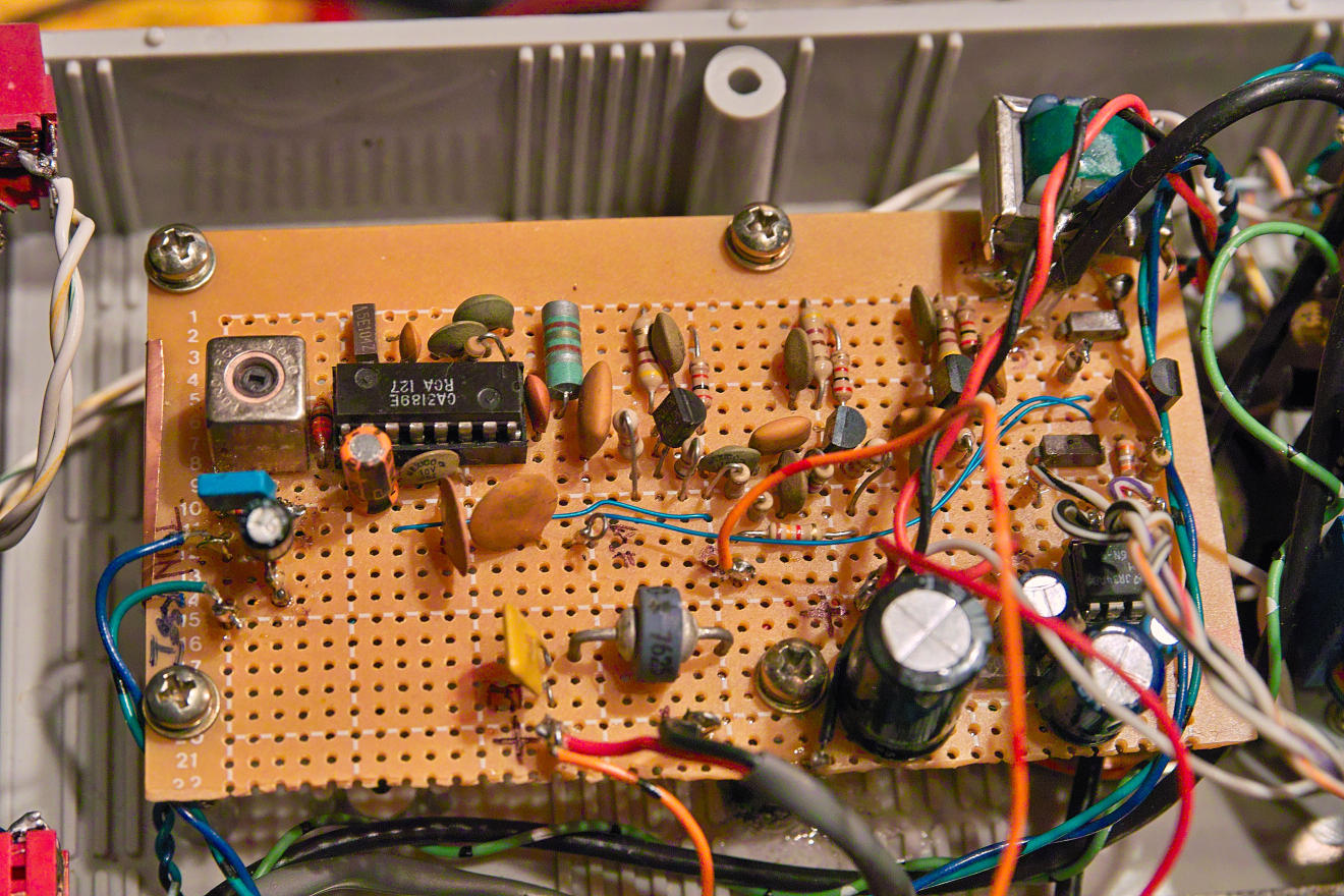
Figure 3:
Top: On the workbench: In pieces, but
working, the Weather Satellite receiver - before it was put
into it's box, of course!
Left to right: Display, CPU board (the small one with
the ribbon cable), the main RF/VCO/PLL board, and the
IF/Demodulator board - before the audio amplifier was added. Bottom: A top view of the receiver after all of
the bits were crammed into a box. Starting from the
upper-right: IF/Audio section (on perfboard),
CPU/Control board (mounted on front panel), LCD (mounted on
front panel), Local oscillator compartment (just behind
ribbon cable), mixer and post-mixer amplifier (left of the
local oscillator, behind the display), RF amplifier and
filter (the coil and the compartment with the cover) and the
frequency reference/PLL board (the one with the box with the
white label.) Click on an image for a larger version.
Even though the signals from the weather satellites are quite
strong when overhead, they can be quite weak when the satellites
are near the horizon. This makes sense when you think about
it:
When overhead, the satellite is as close as
it is going to get, so the signals are stronger.
Most of the satellite's transmitted signal
is beamed downwards so that those receiving stations directly
below the satellite will get the strongest signal.
When notoverhead the ground station below, not only is the
satellite farther away, but that ground station is off to the
"side" of the satellite's antenna, out of the strongest
portion of the beam: These to factors can cause the
signal to become quite weak!
Aside from boosting faint signals, an
amplifier also overcomes the losses in the cable that connects
the antenna to the receiver that would further degrade an
already-weak signal.
For the preamplifier (see Figure 2,
bottom) I constructed a simple GaAsFET
amplifier. This amplifier has a fairly low noise figure
(in the 0.5-0.9 dB area) and modest (about 18dB) gain - both
being sufficient to dig a weak signal out of the noise and boost
it enough to overcome moderate cable losses.
A representative schematic of this
preamplifier may be found here.
Even though this preamplifier is intended for operation in the
2-meter amateur band (144-148 MHz) it is easily re-tuned to
the 137 MHz region. Note that the linked schematic does
not include the bandpass filter or the power-over-coax
coupling.
Following the preamplifier is a 2-stage
bandpass filter: This filter is placed after the
amplifier to minimize losses that would increase the amplifier's
noise figure and reduce its sensitivity. Because GaAsFET
preamplifiers have reasonably good dynamic range, only
very-nearby transmitters (such as my own 2-meter transmission)
are likely to overload it. The filters themselves knock
out signals on other nearby frequencies (such as passing
aircraft) that could overload other stages in the receiver as
well as provide a higher amount of "image
rejection" to prevent signals 21.4 MHz below that of the
desired frequency (which are also in the aircraft band) from
getting into the receiver. Since this filter has a bit of
loss (1-3dB) it should be placed after the preamplifier where this small amount
of attenuation will not
visibly affect signal quality.
To conduct signals from the preamp to the
receiver - as well as to provide power for the preamplifier -
standard RG-6
TV-type coaxial
cable is used with F-type
fittings. This cable is ubiquitous, fairly small in
diameter, cheap, and exhibits fairly low-loss characteristics at
this frequency so it was an obvious choice. Again, to
minimize losses the preamplifier assembly is mounted at
the antenna in a weatherproof enclosure: Doing
so allows a relatively short run of coax from the antenna to the
preamplifier to minimize signal degradation.
Post-preamplifier
bandpass filter details:
As it turns out, a number of people have
emailed me for details on the 2-stage bandpass filter that is
used "post-preamp" to restrict the bandwidth and to make the
receiver less susceptible to off-frequency interference.
This filter can be reasonably expected to improve the image
rejection and to somewhat attenuate nearby 2-meter amateur
transmissions, but it is NOT sharp enough to
reject signals from paging systems that plague some European
users of these satellites: For that, you'll need to use a
1/4 wave notch cavity. This can be constructed of standard
copper water pipe and would be approximately 20" (51cm)
long: Details can be gleaned from the internet.
As can be seen from the picture in Figure 2 this filter
consists of two coils, mostly separated by a shield with the
pair of coils enclosed in a larger shielded enclosure consisting
of approximately 1" (2.5cm) wide strips of double-sided copper
circuit board material, all built on a larger piece of circuit
board material - which could be single-sided if
so-desired. Small countersunk holes were drilled in the PC
board material to allow easy connection to the coils' input and
output taps. Since the preamp and filter was mounted in a
rather shallow metal box, I didn't put a top shield over the
coils but if they had been put in a larger box or anywhere near
a source of noise - such as a computer or digital circuitry then
a shield of thin sheet brass should be placed over the top of
each coil, individually, and tack-soldered in a few points each
with a small hole to access the tuning screws of the trimmer
capacitors.
The coils themselves consist of approximately
8 turns of #14 AWG solid copper from electrical house wire,
close-wound wound on a 0.25 inch form (approx. 6.2mm) and then
stretched after winding to space adjacent turns about 1/2 wire
diameter apart. It is recommended that one coil be wound
clockwise and the other counter-clockwise and placed so that the
"1 turn from ground" tap point (see below) of each coil be located adjacent
to the hole through which the connecting wire (to the tap) is
passed.
The input and output "taps" are located about
1 turn from the grounded end of each coil and 2-20pF trimmer
capacitors are used at the "top" end for tuning and the two
coils themselves are coupled to each other using 0.5-1pF of
capacitance which can either be in the form of one or two 1pF
caps in series, or a small "gimmick" capacitor (e.g. two
separated, insulated pieces of wire twisted together.)
Practically speaking, the way one would wind and mount these
coils, they will have closer to 8-1/2 turns, but because of the
available tuning range offered by the 2-20pF trimmer caps the
actual dimensions of the coil aren't terribly critical.
The gauge of wire can also vary from #12 AWG to #16 AWG,
depending on what is available, but the heavier wire allows the
coil to be self-supporting and rigid.
In this filter I used inexpensive ceramic
trimmer capacitors which are adequate for the job. This
filter is narrow enough that it is best that it be adjusted on the
center-most frequency of interest (about 137.50 MHz) as there will
be some attenuation of the frequencies at the two extremes of the
receiver's tuning range (e.g. the 137.10 and 137.9125 MHz
frequencies) but since this filter is intended to follow a low-noise preamp its slight
additional loss should not measurably affect the overall signal
quality: In other words,
do not put this filter between your
antenna and preamp!
If one wishes to optimize performance of the filter, the
more-expensive glass or porcelain "piston" type trimmers may be
used - along with a 0.5-2.5 pF piston trimmer as the coupling
capacitor between the two filter sections to allow its coupling to
be optimally adjusted using a sweep generator or similar piece of
test equipment. If one really is picky, the coils themselves
could be silver-plated or, at the very least, enamel wire could be
used (or the bare wire sprayed with clear lacquer after the filter
is constructed) to avoid losses due to its oxidation. If an
even "sharper" filter is required, additional sections could be
added, but the proper adjustment of such a filter would definitely require test
equipment and a bit of extra homework to implement to assure
proper inter-element coupling and the desired passband! Receiver front end:
To power the external preamplifier, power is fed to the input coax
via J101, a standard TV-type "F" connector and L101, a 10uH choke
which blocks the received signal while passing the DC to run the
amplifier while capacitors C102 and C103 shunt away any residual
RF that might make it past the choke. DC power is supplied
via Q101 and associated components which form a DC current source,
the purpose of which is to limit the available current should the
RF cable be shorted out to a safe value in the area of 40-60
milliamps - more than enough to run the external
preamplifier. Without it, the full current of the power
supply running the receiver would be present and an accidental
short (easy to do with F-type fittings!) would instantly destroy
L101. Switch S101 allows this voltage to be disabled, if
desired.
The receiver front end is fairly simple - a two-stage bandpass
filter with integral JFET
preamplifier, Q102. For this, a grounded-gate
amplifier, based on a J309, is used with a tuned circuit on the
input (L103 and C105) and output (L103 and C107.) This
amplifier offers modest performance, providing a gain of 10-12dB
with a noise figure of 2-3dB - more than adequate to overcome the
majority of the mixer noise. The filtering of this amplifier
- while not particularly "tight" - is adequate for the
purpose: Remember, there is better (lower-noise)
amplification and filtering at the antenna! As can be seen
from Figure 4 the "input"
coil has a shield placed over it to prevent noise from the digital
circuitry in the receiver from being coupled into it.
There's nothing magic about the J309 (or its cousin, the J310 or
U310) other than it is fairly well- characterized and
low-noise. The cheaper, more common MPF102 would work almost
as well, the difference between it and a better-performing device
being negligible if the receiver is preceded by a mast-mounted
preamplifier.
Even without the antenna-mounted preamp, the 12dB SINAD
sensitivity of the receiver with the JFET preamp alone is better
than a microvolt - good enough to be used with a short run of
low-loss cable and a decent antenna for reception of "high"
satellite passes.
Figure 4: The "front-end" and mixer of the
receiver. On the far left can be seen the antenna
input connector and the current-limit circuit. Under
the shield is a coil - much like the one that is visible to
its right - along with the JFET for the front-end
amplifier. In the compartment on the right is the
image-reject filter, the mixer and post-mixer amplifier. Click on the image for a
larger version.
Comments on coils L102/L103:
The grounded-gate preamplifier depicted in the schematic
has appeared in the ARRL Radio Amateurs Handbook for decades
and was originally intended for 2 meters (144-148 MHz) but is
easily retuned for the 137 MHz area with little or no
component modification.
Coils L102 and L103 are identical (aside from the taps) and
consist of about 4-1/2 turns of #12-#16 wire wound on a 5/16"
form and then stretched to space windings by about 1/2 a wire
diameter. For L102, the input tap is 1 turn from ground
while the FET's source is connected at 2 turns from the ground
end. For L103, the output is tapped at 1 turn from the
"cold" end (e.g. that
opposite the tuning capacitor) while the FET's drain
lead is connected at 3 turns from the "cold" end.
Note that the "1/2 turn" comes from the way the coils and
tuning capacitors are connected and mounted, but practically
speaking 4-1/2 to 5-1/2 turns would be OK as the values aren't
terribly critical and variations can be accommodated by C105
and C107, the trimmer caps. Aside from mounting these
coils and trimmer caps for good mechanical stability within a
shielded portion of the enclosure (particularly L102!) the
important consideration is C115. For this, I used a
solder-in feedthrough capacitor as it provides both good
electrical charactersitics and
a solid mechanical mounting point. Practically speaking,
a good quality disk-ceramic capacitor could be used instead
(in the 1000-4700 pF area) but remember that this capacitor's
role is to make that end of the coil appear to be an RF
ground and that leads must be kept quite
short. Were I to use a capacitor other than a feedthrough
type, I'd use two small 1000 pF disk or monolithic ceramic
capacitors together, both to provide good mechanical stability
and to assure a solid RF bypass to ground.
Mixer:
The signal from the preamplifier goes to a diode-ring passive
mixer U101 - but between the input and ground is a simple, series
L/C circuit consisting of L104 and C109 that is tuned to the image
frequency of the receiver (lower than the receive frequency by twice
the IF frequency, or 21.4 MHz below) around 116 MHz. This
provides at least 20dB of additional image rejection, yielding
about 55dB overall of image rejection to the receiver.
Again, this figure is "adequate" but not great, remembering that
there is more filtering at the antenna that improves the image
rejection to well above 75dB. Refer to
schematic pg. 1
A standard diode-ring mixer, a Mini-Circuits
RMS-11X, is used at U101. This is a passive device, having
good dynamic range and requiring only a local oscillator to
convert signals. Because it has a fairly high insertion
loss (around 7 dB) it is necessary to precede it with the
preamplifier described above to achieve good system
sensitivity. Even though this is a surface-mount device,
it may be used with "dead bug" construction if heavy ground
conductors (such as copper foil) are used to interconnect its
ground leads to the receiver's ground plane.
Following the mixer is a very simple
"highpass/lowpass" diplexer to assure that signals being outputted
by the mixer (particularly the "local oscillator plus receive
signal" image that is at about 260 MHz) are properly
terminated: C102 and R108 are chosen to provide something
resembling 50-ish ohms at the image frequency while the
combination of C114 and L105 form a broadly-resonant circuit to
allow the 10.7 MHz-area signals to reach the post-mixer amplifier,
Q103. It's worth noting that the failure to terminate the
mixer at both the desired and image signal frequencies
resulting from a conversion can result in undesired mixing
products, potentially reducing receiver performance considerably,
especially in the presence of other signals within the passband of
the pre-mixer RF filtering. Since there is always a bandpass
filter preceding the mixer there aren't really any significant
signals present other than the sum and difference mixing
products. The post-mixer amplifier, Q103, is designed to
terminate the mixer at around 50 ohms.
The amplified signal from the mixer, now at the I.F.,
is further amplified and broadly filtered by several amplifier
stages, each using "standard" 10.7 MHz ceramic IF filters with
150-230 kHz bandwidth. After passing the last IF amplifier
stage, Q203, the signal is passed through a narrow (40 kHz)
ceramic filter, CF203, and it is this last filter that sets the
ultimate bandwidth of the receiver. While the 10.7 MHz, 40
kHz wide ceramic filter isn't particularly "sharp", it seems to be
more than adequate in eliminating adjacent-channel signals - such
as those from the Orbcomm satellite
network. C208 and L202 roughly match the 600-ish
ohm output impedance of the ceramic filter to the 50-ish ohm input
impedance of U201 and its associated circuitry.
Initially, I was worried that having fairly wide-bandwidth
filtering in the early IF stages was going to make the receiver
susceptible to interference from nearby Orbcomm satellite and
Aeronautical traffic - either of which can be within a MHz or two
and for this reason I originally had a 40 kHz filter installed at
CF202 as well. Because of the fickle nature of ceramic
filters and the fact that their bandpass response is often
less-than-ideal (that is, not particularly "flat" across their
passband, but a more "rounded" curve) I observed some degradation,
particularly on weak signals that were slightly offset in
frequency due to Doppler shift, so I replaced it with a 150 kHz
wide filter which resolved the problems. I was initially
worried that this would make it more-susceptible to
nearby-frequency interference, but "on-air" testing has not
revealed any tendency for this to happen.
Figure 5: The IF amplifier and audio
board. The 10.7 MHz IF signal enters at the right and
passes through several filter/amplification stages.
U201 - the demodulator chip - is seen, along with the
quadrature coil. Toward the lower-right corner of the
board can be seen U202, the LM386-4 audio amplifier. Click on the image for a
larger version.
The demodulator
uses the venerable LM3189 chip, U201. This is a fairly
easy-to-use IC and although it is obsolete, it is still readily
available on the surplus market: I used it just because I
happen to have a bunch of them onhand. This chip contains a
limiter and quadrature detector and provides both an "AFC" output
(Automatic Frequency Control - for determining if the received
signal is on-frequency) and an "RSSI" (Received Signal Strength
Indicator) output: The former can be used to track Doppler
shift, if desired, and the latter can be used to provide a signal
strength reading.
The value of L201 and its capacitor can be determined from the
LM3189's data sheet, but it isn't critical. The easiest way
to come up with a suitable combination is to use a 10.7 MHz IF
transformer from a discarded FM receiver with the other winding
(the one without the
resonating capacitor) left disconnected. What is important is that it be
shielded and that the coil/capacitor combination inside be
adjustable so that it will resonate at 10.7 MHz. Final
adjustment consists simply of tuning in a modulated signal
centered in the IF and adjusting L201 for the highest audio output
level with the "cleanest" signal. Ideally, one would use a 1
kHz tone modulated to +/- 20 kHz deviation and use an oscilloscope
to obtain the best-looking and highest-amplitude sine wave, but
this can be done by ear or with one of the many "sound card
oscilloscope" programs that are available for free while
monitoring a signal from a weather satellite.
Note:
L201 is typically
an inductor in a shielded can with a built-in capacitor.
Typical values for this built-in capacitor vary from 12pF to
47pF, depending on the coil/transformer and its original design
requirements implying an inductance range of L201 somewhere in
the vicinity of 4.7 to 18 uH. Again, this inductance value
isn't critical. Practically speaking, a fixed inductor
could be used along with a trimmer capacitor, but if you do this
remember to enclose the combination in a bit of shielding to
prevent the pickup of stray signals.
When using this chip it is important that good
wiring practices be employed with sufficient RF bypassing.
Failure to do this can cause the LM3189 (or its predecessor, the
'3089) to do odd things, most commonly "seeing" a signal that
isn't there as evidenced by elevated RSSI readings when no actual
input signal (even noise) is present. Despite all of these
precautions, I originally found it necessary to use as much
"pre-limiter" gain as I did in order to assure that, with the
receiver running "barefoot" (that is, just the JFET preamp and not
the external preamp) that there was at least some RSSI indication
on the receiver's own noise floor.
In order to keep high-gain RF circuits like this happy, it's
imperative that a good RF ground is provided - something that is
difficult to do on perforated proto-board like this. For
this reason I have strips of self-adhesive copper foil along
portions of the bottom of the board: Without it, it is
possible that some of the signal from U201 will find its way back
into the input and cause instability which would degrade
performance. A bit of this copper foil is just visible along
the left edge of the board as it wraps around to the top side.
Comment:
I later discovered a minor wiring
error that reduced the level of the IF signal: Now,
everything works as it should - more details are at the bottom
of the page. Remember: You learn more by making
(and fixing) mistakes than you do if everything goes right the
first time!
The demodulated "audio" output of this chip is
buffered by Q204 and related component with R226/C226 offering a
degree of de-emphasis/lowpass filtering (mostly to remove
high-frequency noise components) and made available to the
computer doing the processing, this being done to minimize
unintentional degradation of the received images due to the
possibility of noise at frequencies above the Nyquist limit (e.g.
1/2 the sample rate) entering the sound card and aliasing.
The components shown (1k and 0.1uF) produce a -6dB "knee"
frequency of around 1600 Hz.
Note: Not
shown in the schematic is a 1:1 audio transformer (600 ohm) that
is used to prevent a ground loop between the receiver audio line,
the computer, the antenna, power supply and station ground -
something that could introduce hum under certain conditions.
Also included is an audio amplifier, U202, based on the LM386, that is
used to drive a speaker. While an "S-Meter" squelch (one
that is based on signal strength rather than signal quality) could
have been implemented with the LM3189, I have not done so - hence
the reason that the second control isn't connected, and since the
computer doesn't really care if it "sees" noise all of the time
that there's not satellite being received, there doesn't seem to
be any real reason to do so. Since I only turn up the volume
occasionally to see if things are working properly, the constant
"hiss" doesn't bother me!
Figure 6: The local oscillator
module. The micro-coax resonator may be seen in the
upper-right corner. Click on the image for a
larger version.
The local
oscillator is a simple Colpitts
circuit using an MPF102 JFET at Q301 and it
operates 10.7 MHz below the receive frequency. The inductor
L301 uses some extremely small-diameter (about the size of #18 AWG
wire) PTFE"hardline"
coax forming a 1/4 wave resonator. While I could have
simply used a standard inductor/capacitor arrangement, I was
curious as to how well this 1/4 wave transmission line resonator
would work. One advantage of this method is that it is
less-sensitive to microphonics - that is, the tendency for
mechanical vibration to modulate the oscillator, the result ending
up back in the receiver audio which, in the worst-case scenario,
can cause feedback with the loudspeaker. This oscillator has
also been proven to be quite stable, providing a reasonably clean
CW "note" when tuned in with an SSB receiver that is more than
adequate for FM use.
In testing I have found that the local oscillator is very
insensitive to microphonics
despite the fact that the speaker is only inches away and that
most of the tendency for microphonics is, in fact, from the
mechanical vibration of Q301 and its associated components.
As such there is no obvious tendency of the receiver to "ring" due
to microphonics and there is very little effect on the received
pictures (due to microphonic action) when the audio amplifier is
turned all of the way up indicating that this experiment was
successful.
A varactor diode
D301 is used to tune the oscillator and a range of about 126.0 to
129.5 MHz is provided, covering all possible satellite frequencies
in the 137 MHz range, plus allowing the receiver to tune to 140
MHz: This 140 MHz tuning capability is provided solely to
allow the receiver to tune in a harmonic of the 20 MHz CPU
clock/reference signal that could, in theory, be used in the
receiver and allow a means of self-calibration in terms of the
receiver tuning and the AFC.
Following the oscillator are two emitter-follower
buffer amplifiers: The first of these, Q302, isolates the
oscillator from the rest of the circuitry while the second, Q303,
isolates the oscillator yet again, providing a drive signal to the
synthesizer section, described below. This isolation is
important as the synthesizer section contains a frequency mixer
(Q401 - see below) that could inject spurious signals into the
local oscillator signal and degrade receiver performance.
The output of Q302 goes to yet another stage of amplification,
Q304, which boosts the local oscillator signal to about +7dBm to
drive the diode-ring mixer, U101.
The power supply for the VCO
and buffer comes from U301, a 78L09 regulator. This device
provides a clean, stable source of power for the VCO to prevent
changes in the power supply voltage from affecting the frequency
or modulating the local oscillator. This voltage is also
used to provide clean power to the 100 MHz VCXO used as the
receiver's master frequency reference - see below.
In order for a frequency
synthesizer to work with good accuracy, a stable frequency
reference is needed. In this case, a 100 MHz VCXO
(U401, a Voltage-Control Crystal Oscillator) is used: This
device was rescued from a piece of scrapped satellite equipment
and has been found to be stable to better than +-1kHz over a
fairly wide temperature range - adequate stability for our
purposes. The output of this oscillator is amplified to
"TTL" level by Q404 and fed to U403, a 74F191 wired as a
"divide-by-5" counter to produce a 20 MHz signal that is used to
drive the CPU.
The 100 MHz output also goes to a
single-transistor bipolar mixer, Q401, where it is combined with a
sample of the 126-130 MHz buffered output of the local oscillator
from Q303. The 26-30 MHz output from this mixer (the
"difference" between the 126-130 MHz local oscillator and the 100
MHz VCXO) is low-pass filtered by C405-C407 and L402-L402 and then
amplified by Q402, broadly filtered again by C413 and L404 and
amplified to "CMOS logic" level by Q403 before being inputted to
U402, a 74HC4040 binary
counter, where it is divided by 4096 to produce another
signal that is in the 6.3-7.3 kHz region. It is this
frequency that is compared with the PLL reference signal generated
by the CPU in the PLL.
Figure 7: The LO Converter, Master
frequency reference and PLL board.
The audio-frequency reference from the CPU comes in at the
upper-left and is filtered and fed to the PLL chip. On
the upper-right is the LO converter that "subtracts" 100 MHz
from the local oscillator signal. The box with the
white label is the 100 MHz VCXO. Click on the image for a
larger version.
The Phase-Locked
Loop (PLL) is used to control the frequency of the
VCO. It does this by comparing the frequency of the
down-converted LO (the 6.5 kHz-ish signal from U402, the
74HC4040) with a locally-generated audio frequency being used as
a reference - also in the 6.5kHz range: This latter
frequency is chosen to be the same as that which would be
produced by the VCO's down-conversion if it happened to be on
the correct frequency. The receive frequency is related to
that down-converted frequency in this way:
Down-converted (audio) frequency (in
kHz) = ( (Receive Frequency in kHz - 10700 kHz) - 100000 kHz)
/ 4096
The PLL reference signal, generated by the CPU
(and discussed below) is inputted to a bandpass filter consisting
of U501C and U501D. This filter takes the rather "rough"
signal from the CPU and filters it to produce a clean sine wave,
using D501 and D502 to limit it to a constant amplitude. The
output of this filter is then passed to a "slicer" consisting of
U501A, R507 and C504, the output of which is a nice square
wave. This is then fed to U502 via R508, which effectively
allows the 0-12 volt square wave from U501A to drive U502 which
only needs a 0-5 volt signal.
Comment: It was later
determined that this bandpass/limiter filter was probably not
necessary as the loop filtering proved to be adequate.
Since it was already built and working, I didn't bother
removing it!
The PLL chip, U502 - a 4046 - compares the
phases of the down-converted signal with the locally-generated
signal and if the VCO is too-high in frequency, it steers the
VCO's frequency downwards and if it is too low, it steers it
upwards. With the proper selection of time-constants, the
VCO would immediately "snap" onto the desired frequency with good
stability.
To do this "frequency steering" a "loop filter" is employed on the
output of U502 consisting of U501B and associated
components. The heart of this circuit is U501B and its
associated capacitors, forming an integrator that takes the
varying pulse-width from U502 and smooths it to a voltage that
will appropriately move the VCO up and down.
On the input of this loop filter are a number of additional
components: R510, a 1 Meg resistor, together with C510 and
C509/R511 have a rather long time-constant to provide considerable
filtering of the tuning voltage to remove all traces of the
audio-frequency reference signal. If these were used alone,
it would take a rather long time for the synthesizer to tune from
one frequency to another (perhaps 5-20 seconds) - a lock time that
I considered to be unacceptable - at least to someone tuning the
receiver manually but practically speaking, in automated
weather-satellite use this would not be a problem as the receiver
is tuned to the proper frequency at the beginning of the satellite
pass and the loss of a few seconds of signal would be of no real
importance.
To speed up the tuning additional components were added:
R509, a 33k resistor, works with D503 and D504 and only
larger-sized changes in the output from U502 will "break over"
those diodes. The output from these diodes is filtered by
C508 and this voltage is then applied to Zener diodes D505 and
D506. These series-wired diodes don't conduct until the
voltage exceeds 3 volts, but once they do, capacitors C509 and
C510 are charged/discharged very quickly. The effect of this
is that when the frequency is "way off" U502 will slam to full V+
or ground and the extra diode circuitry will conduct,
quickly steering the local oscillator. Once the frequency
gets "close" to its intended target the output of U502 will
decrease and these diodes will no longer conduct and the "slow"
time constant of R510 will again take over. It is this "dual
time constant" that allows the best of both worlds - "slow" filter
that permits a clean, stable output for keeping the local
oscillator on-frequency and a "fast" one that allows any frequency
to be tuned in under a second.
Display user data (such as frequency) on
the front-panel LCD.
Take user input - such as that from
pushbuttons - to change frequencies, etc.
Digitize data such as signal strength so
that it can be displayed.
Take input from the computer for remote
control.
Generate a precise audio loop reference
frequency for use by the PLL.
Q601 buffers and amplifies the 20 MHz signal
from the PLL board and feeds it to the CPU, U601. The PWM
output of the CPU is coarsely filtered by R602 and C604 to remove
the highest-frequency components that might otherwise find their
way into the IF or RF circuitry and Q602 is a simple inverter that
takes the RS-232 signal from the controlling computer and converts
it to a voltage compatible with the CPU's logic input, using the
chip's on-board pull up resistor.
Figure 8: The CPU board. The
processor generates the precise audio frequency for the PLL
reference as well as driving the LCD (display), reading the
pushbutton(s) and receiving serial-port commands. Click on the image for a
larger version.
The CPU, a PIC16F88, does all of these functions
using its onboard peripherals: For the audio
frequency-generation, its onboard PWM
hardware is used as a simple D/A converter and DDS
(Direct Digital Synthesis) techniques are used to produce a sine wave with
10 bits of resolution. The DDS software was written to use a
32 bit accumulator which means that the audio frequency can be
very-precisely generated in steps of about 0.000005 Hz - yes,
that's 5 microHertz!
Because the downconverted frequency is related to the local
oscillator frequency by a division-by-4096, that means that the
local oscillator frequency (at 126-130 MHz) can be controlled with
far less precision than that of the reference frequency - but
still, to within 0.02 Hz! While this amount of precision is
meaningless when it compared with the absolute stability of the
100 MHz reference oscillator and and the precision required when
tuning in an FM signal, it was easy to accomplish in software and
provides more than adequate frequency resolution: A DDS
synthesizer with only 16 bits of accumulator resolution (the next
"logical" step downwards in terms of software) would provide steps
of about 1.3 kHz - a size that I considered to be too
coarse. Because the CPU is clocked from the 20 MHz signal
originally derived from the 100 MHz oscillator, it has a stable,
accurate reference for the generation of the local oscillator
frequency, holding frequency to 1-2 kHz over a wide temperature
range.
For those readers more familiar with the design of DDS and PLLs,
eyebrows might be raised as to the use of techniques with such a
large divisor ratio! One concern would be the inevitable
spurious responses intrinsic to DDS synthesis causing undesired
phase modulation of the 6.3-7.3kHz reference signal. With
fairly aggressive loop filtering (e.g. fairly long time constants)
and the careful selection of the DDS clock frequency, one can
"relocate" these spurious responses away and out from the loop
filter's bandwidth and generate audio frequencies with sufficient
cleanliness so that undesired "reference sidebands" are attenuated
adequately by filtering. Additionally, relatively simple
techniques of using a "dual time constant" in the PLL's loop
filter can allow the receiver's local oscillator to be
on-frequency in well under a second, even with such aggressive
loop filtering.
In addition to generating the reference frequency for the local
oscillator, the CPU also drives U603, a 2-line by 16 character
LCD. This display is operated in the "4-bit" mode to reduce
the number of connections to the CPU. Because the CPU has a
limited number of I/O pins, the two pushbuttons are also connected
across the data lines that feed the LCD and when the display is
not being updated, the status of these buttons are being
read. While one of these pushbuttons is used to select a
pre-programmed weather satellite frequency (plus the 140 MHz
"calibration" frequency) the other is presently unused - mostly
because I haven't quite figured out what to do with it!
Another job of the CPU is to digitize some analog input voltages
from the AFC circuit (to determine offsets from Doppler shift) as
well as the RSSI output (to determine signal strength) and display
them - although neither of these parameters are currently used for
anything other than the values being shown on the LCD.
The LCD - a surplus 16 character-by-2-line unit - displays not
only the frequency being received, but also signal strength and
frequency-offset readings - mostly for my curiosity.
Finally, as mentioned above, the CPU also contains a UART that can
receive serial commands from the computer running the WXtoIMG
weather satellite image decoding program that not only tells the
receiver what frequency to select, but also when the computer is
processing a signal - a case in which the CPU puts an "RX" on the
display to let one know that a satellite pass is in progress!
Measured performance:
Using my trusty service monitor, here are some measured
specifications:
Sensitivity (1 kHz tone, +/- 20 kHz
deviation), measured at the audio output to the computer with
the test signal applied to the receiver input and not
through the GaAsFET preamplifier:
12dB SINAD: -114dBm (0.45uV)
20dB SINAD: -111dBm (0.63uV)
The above SINAD
values include the effects of pseudo de-emphasis imposed by
R226/C226 on the "Audio Out" jack as this roll-off of higher
frequency energy can increase the measured SINAD over raw
"discriminator" audio. (With
the values noted - 1k and 0.1 uF - the -6dB "knee" frequency
is around 1600 Hz, so it's not the same "PM" de-emphasis as
used in narrowband terrestrial communications.)
Doppler shift tolerance: With a test
signal at -110dBm modulated with a 1 kHz tone at +/-20kHz
deviation, a frequency error of +/- 3 kHz can be tolerated
without any degradation in distortion or signal/noise.
Selectivity:
-3dB: +/-20kHz (40 kHz BW)
-6dB: -23/+27kHz
-10dB: -25/+35kHz
-20dB: -30/+47kHz
-40dB: -35/+52kHz
Image rejection: At least 55dB at
137.500 MHz. At least 20dB more image rejection than
this is provided by the filtering in the mast-mounted
preamplifier.
Again, it should be remembered that there is
also mast-mounted GaAsFET preamplifier with a bandpass filter is
placed ahead of this receiver, so the actual sensitivity
should easily reach that of the thermal noise limit (that is,
Earth, atmospheric and electrical noise would be the limiting
factor for the receiver's performance and not its
intrinsic sensitivity.)
Disturbances to the pictures:
Having built the receiver several years ago and
having it powered up continuously since then, it seems to work quite
well as can generally be seen from the pictures. The dark bands that
may be seen are generally due to blockage from local trees causing
momentary fading of the received signals - something that could only be
helped with a relocation of the antenna to a higher, clearer location.
In
the past one could see "wavy lines" in many of the pictures and
listening to the audio I could hear a slight amount of AC mains-related
noise. For a while I was not sure of the source of this interference,
whether it was local - something in my house or a neighbors - or
farther away, but 5-6 years ago (around 2010) the local power company
completely replaced a run of large power lines in a corridor several
blocks to the east and the noise has not returned since.
Final comments:
Were I to build another receiver from scratch, there are a few
things that I might do differently:
IF amplifier/filter stages.
There are more-modern devices than the LM3189 device used that
have better "raw" sensitivity and would have required fewer IF
amplifier stages, but since everything works, so what!
As noted above, I finally found a minor wiring error that
caused the IF amplifier chain to have about 20dB less gain
than it should have. In correcting this mistake, I was
able to remove an extra IF amplifier/filter stage that I'd
originally added just after the post-mixer amplifier and the
FM limiting performance has also improved. The need for
this extra stage had bugged me from the beginning as the
numbers just didn't add up and it should have worked
better than it did without it. Now that it's fixed, it
works as expected!
Improve the physical layout.
Since the receiver was built and tested one section at a time
and then crammed it into a box, it's not laid out quite as
well as I'd like - but that's mostly nit-picking as I've not
experienced any real problem with it due to this.
Is this design ideal? No, of course not -
but that's not the point! I just wanted to try my hand at
putting something like this together with stuff that I had laying
around and were I truly serious about the ultimate in
design/performance/elegance/simplicity I'd have done things
differently!
So, would I recommend that someone wanting to build a weather
satellite receiver duplicate exactly what I've done? No, but
that's because I'm sure that some things could be done better!
Schematic
errata and comments:
Over time, I've noticed (and tried to correct)
errors in the schematics as well as added information that will
(hopefully) clarify things a bit. An incomplete list of
these changes include:
Added details for JFET amplifier coils L102
and L103.
Added missing bias resistor for Q101, the
antenna current limiter (now R101)
Fixed incorrect designations and values for
what are now R606 and R607 (bias resistors for Q602, the 20
MHz clock amplifier for the CPU)
Fixed error in representation of L201, the
10.7 MHz quadrature coil: Removed value/designation of
its built-in tuning capacitor and added a note.
Made parts designations more consistent
throughout.
Other
things that I can't think of at the moment...
A small supply (e.g. one set per
person!) of some of the parts (40 kHz wide ceramic filter and
some of the micro-coax) are available. Also available is
programming for the PIC16F88 chip used - contact me via email
using the above link.
This page
maintained by Clint, KA7OEI and is copyright 2008-2015. Last update:
20150415


