
|
If you have the ambition, time, the skill (or is it daring?) and/or money burning a hole in your pocket, there are a number of things that you can add to the FT-817 - obstensively to make it "better."
My '817 has been fairly heavily modified/accessorized. These include:
Note: The One Board Filter is available (only) as a
factory-installed
option (as far as I know) and its installation isn't discussed
here.
The "One Board Filter," the "One Big Punch" and the "Hear-It" modules
(for
the FT-817) are available from W4RT
electronics. See the note
at the bottom of the page for more info.
Note: I have no pecuniary interest in W4RT electronics. It just so-happens that they have a lot of '817 "goodies." The "OBP" and "OBF" are trademarks of W4RT Electronics.
The OBP is an audio speech processor based on the Analog Devices SSM2165 audio processor. This chip contains circuits for compression and noise gating that, when properly configured, can increase the average power contained in the speech.
How effective is this? The OBP is intended primarily for applications where the signal to noise (S/N) ratio is rather poor - or, in other words, SSB under weak/noisy signal conditions. Being that the "talk power" of an SSB signal is related to the amplitude of the audio being fed into the transmitter, it would make sense that if the overall energy of the voice is increased, the overall S/N might also be improved.
There is a problem with simply increasing the microphone gain,
however:
Human speech has a rather large "peak to average" ratio - that is, the
loudest parts of the speech are quite a bit louder than the quietest
parts.
What this means is that while some speech sounds may carry pretty well
(most vowels, for instance) some of the unvoiced speech sounds
(consonants
like "f," "h," and "s" for example) are much quieter and may not carry
very well - or be "quiet" enough that their distinctiveness is "lost in
the noise." What this ultimately means is that certain words are
missed owing to key lost sounds - the "quiet" sounds - of the speech,
making
copy tedious or impossible.
 |
If you have your microphone already set for maximum power on voice peaks, increasing it more (to accommodate the "quieter" speech parts) will simply cause overdriving - and possibly distortion. While the ALC of a modern radio can prevent overdriving and/or distortion, it should not be used as a substitute for properly-processed audio.
The idea behind speech processors is to dynamically follow the speech, increasing the the audio gain during quiet parts and decreasing it during the loud parts. In reality, this is rather tricky, as one must carefully balance parameters such as "how much" to increase/decrease the audio gain and "how fast" do you respond to sudden increases in audio gain - and the sudden decreases. I'm certain that everyone reading this has heard examples of "over-processed" speech on the radio - sometimes to the point where intelligibility is degraded somewhat. Under most band conditions, one can run a properly adjusted processor and no-one on the receive end will realize that it is even on! In other words, the processor will increase the "punch" - but it won't sound too "heavy."
Owing to the lack of (extra) interface capability on the '817, there aren't any knobs on the OBP: There simply isn't a convenient place to put them and yet have them accessible to the user in any convenient way. For this reason, the "settings" on the OBP are preset and fixed: Fortunately, these settings have been well chosen for typical use with the stock microphone..
Installing the OBP:
The OBP is constructed on a small circuit board using Surface Mount (SMD) technology and is small enough to be placed either in the FT-817 itself, or in the MH-31 stock microphone supplied with the '817. The advantage of putting it in the microphone is that there is already a switch on the mic that can be used to enable/disable the processor. The obvious disadvantage of this is that the processor goes with the microphone - and you also lose functionality of the "A/B" switch on the MH-31. Not only this, one cannot power down the OBP except by unplugging the microphone - not so much of an issue, however, as the OBP consumes only minuscule current.
Not being satisfied with the "in-mic" installation of the OBP, I opted for putting it inside the '817 itself. Although the radio is small - and a fair amount of room was already occupied by the OBF (the SSB/CW filter board) - there was enough room to install the OBP along the right-front edge of the main chassis. The obvious disadvantage of putting the OBP inside the radio was that one couldn't turn it on or off.
Not without some modification, anyway...
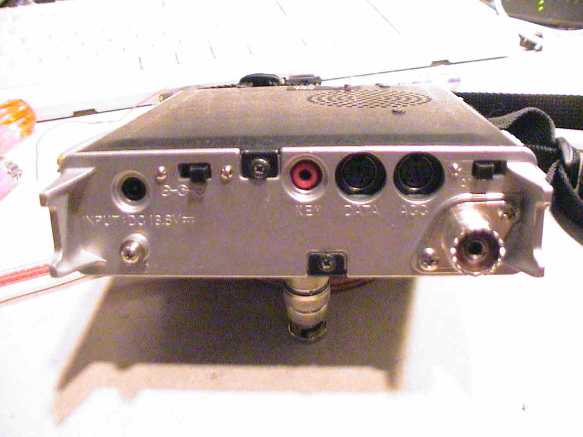
I observed that there was actually a suitable place for installing a small DPDT slide switch on the back panel, next to the external power connection. Knocking a hole in the back of the '817 required several somewhat arduous steps:
WARNING: Do NOT even consider doing this modification unless you have the skill to do so. Furthermore, DO NOT drill/file the chassis unless you have completely removed all of the circuit boards AND cleaned the chassis to remove all traces of aluminum filings! If these filings get onto the circuit board and into various components, you can kiss your radio good-bye!
When all was said and done, the switch was wired thusly:
The OBP was stuffed into a piece of tight-fitting heat shrink tubing
and rests alongside the OBF. Additionally, I passed the audio
input
and output leads through ferrite beads and then passed all
leads
to/from the OBP through one larger bead. (I supplied some of the
beads myself.)
 |
Using the OBP:
The first test was on SSB: I noticed immediately that I had to adjust "mic gain" in the menu significantly downwards. As it turns out, with my voice, I was actually causing a fair amount of ALC action when using the default setting (of 50) and the combination of the OBP and the ALC made my voice sound very heavily processed. Testing on FM and AM showed that I had to do similar reductions in level to make the audio sound tolerable. When the OBP was bypassed, the audio sounded just fine - not appreciably lower than before.
When applying power to the OBP, it takes several seconds for the
circuitry
to stabilize: Bear this in mind if you are doing an A/B
comparison.
Reports indicate that it definitely adds a bit of extra "punch" to the
audio without being overly processed. I generally try to be nice
to others when there is "armchair copy" and not subject them to
the processor - but it can come in handy when conditions and signals
are
less than optimal.
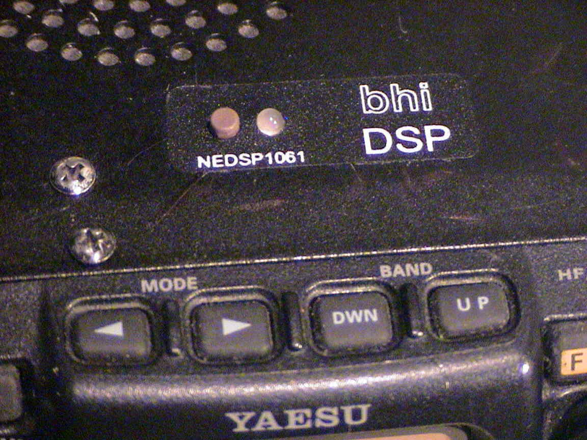
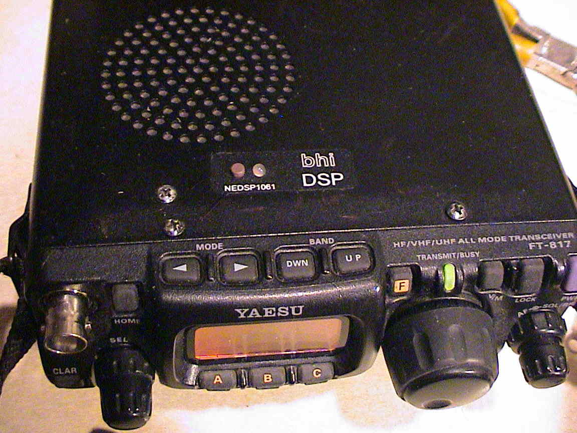
The "Hear-It" DSP audio board is made in England by bhi and is small enough to be crammed into the '817 - even with the OBF and OBP installed. Normally, the "user interface" (which consists of a pushbutton and an LED mounted in the lid of the '817) is all that is installed, but upon testing of the DSP module, I observed that, when operating, it consumed 39 mA and when in "bypass" mode it consumed 45 mA - the extra 9 mA presumably being from the red LED that indicates "bypass" mode.
Hmmm... 45 mA - that's roughly 15% of the total current
consumption
of the '817's receiver! It would be nice if that could be
disabled
when you didn't need the DSP...
 |
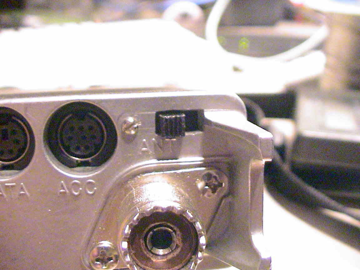
This called for another slide switch on the back of the '817 - but where to put it? The most obvious place to put one was already occupied by the one I'd installed for the OBP. A bit of thinking and measuring provided the answer: Just above the rear panel RF connector.
Again, the same steps were followed (that is, removing the boards, measuring, drilling holes, etc.) to install this switch. There was one catch, however: The switch was to be placed between the "ACC" plug and the "foot" on the back of the '817. This required a slightly different approach in mounting the switch:
When done, the switch was wired much like the OBP:
 |
Final installation of the DSP board:
The optimal location for the DSP board would be in a space currently occupied by the OBF (filter board) so the "alternate" location was used instead. This location is rather hard to describe - but suffice it to say that it is in relatively close quarters.
The installation of the "control board" is done by drilling two small holes in the proscribed locations and then "affixing" that board to the lid of the radio. This last step was actually one of the most awkward, as there isn't really any good way to do it: The manual suggest "hot set glue or epoxy" but a brief experiment with the thermoset glue indicated that it would not work (it doesn't stick well to the metal) so I ended up using "5 minute" clear epoxy.
While this epoxy allegedly sets in just 5 minutes, the switch needs to be immobilized for far longer than that - overnight, actually. This was accomplished using a wooden clothespin and a large bolt (to weight it down.) Despite some care (and warnings in the manual) I still had managed to get some epoxy in the switch - but I was able to remove it (using a straightpin) before it had set - so no harm done.
After installation and wiring, the audio levels were adjusted. In my case, I set the output level on the DSP board to maximum and then set the input level such that the audio through the DSP board when it was in "bypass" mode (that is, the red light is on) was the same as that when the "in/out" switch was set to remove the DSP board from the circuit. While there is a slight amount of residual "digital" noise from the DSP board, it was of such a low level that I didn't find it to be at all objectionable.
The second trickiest task was to route the cables and affix the DSP board. The board is actually attached to the radio's lid using supplied double-sided foam tape - but getting it into place is rather awkward. The trick is to apply the tape to the board, nest the board in its proper location amongst the 817's main board components, hold it into place using some thin screwdrivers whilst simultaneously closing the lid on the '817. After a few seconds, one carefully opens the lid and, if all goes right, the DSP board has "stuck" itself to the proper place and you press it down firmly. Assuming that one has successfully done that, you now have an '817 that's fully decked out with lots of bells and whistles...
A word about the audio from the rear-panel "DATA" jack:
Please note that the recommended installation places the DSP board in the audio path after it is taken off for the "DATA" connector!
In other words, the audio from the back panel will not
be processed by the DSP board. Why was it done this way?
Running
audio containing digital signal through the DSP board (such as PSK,
SSTV,
etc.) will likely be badly distorted by the DSP board and possibly make
copy impossible.
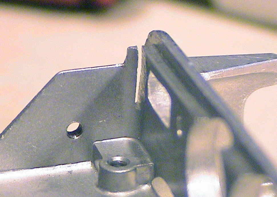
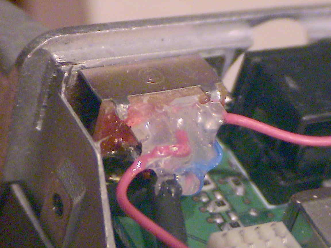
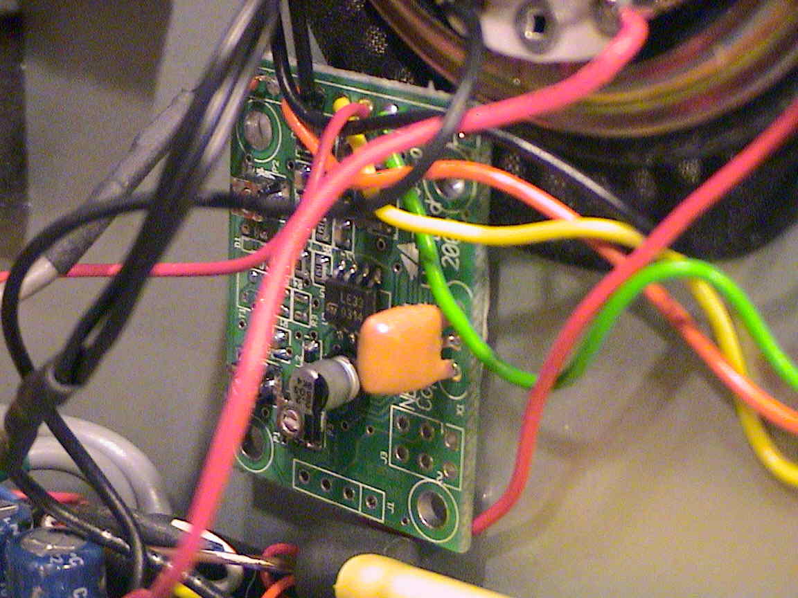
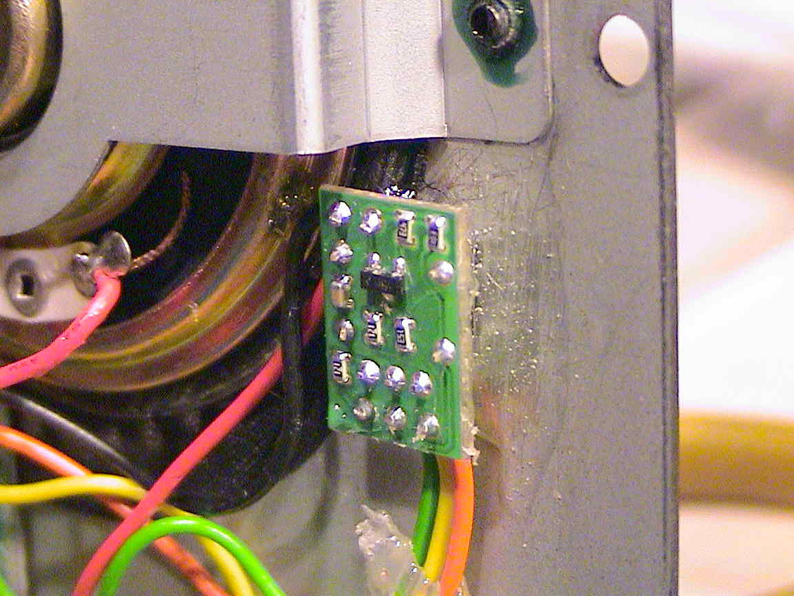
A few pictures:
Below is a collection of pictures of the various pieces that might
serve
to further illustrate the installation. In particular, note how
the
"foot" on the rear panel of the '817 was filed flat to accommodate the
DSP's on/off switch (see the center-left picture.)
 |
 |
 |
 |
 |
 |
"How well does it work?"
I'd say "surprisingly well." It does a remarkably good job of removing AC line noise and it does a good job of reducing "hiss" and other atmospheric noise while adding a minimum of artifacts.
A side-by-side comparison of this board and a Kenwood TS-570S revealed that the "Hear-It" board, when set for comparable amounts of noise reduction, did a far better job than the DSP in the TS-570S: While the DSP on the '570 worked OK, it added a strong, "hollow voices in a barrel" quality to the audio that, in my opinion, sacrificed intelligibility.
The '570's DSP is a bit more flexible in other ways: It has
provisions
for an automatic notch filter that may be activated independently of
other
functions. It also provides a bit of audio high and lowpass
adjustment
capability as well. While this level of functionality may
technically
have been possible in design of the "Hear-It" module, the design
approach
was one where operation was reduced to its simplest level and the
fewest
number of controls - but I wish that "hooks" had been added to
(optionally) provide this sort of flexibility.
A few comments on the DSP module are warranted:
Other FT-817 pages
at this site:
The KA7OEI FT-817 "Front Page" - This is, well, the "front" page of the '817 pages here...
Any comments or questions? Send an email!
This page maintained by Clint Turner, KA7OEI
and
was last updated on 20150415. (Copyright 2001-2015 by Clint
Turner)