The as-built PIC TDOA RDF prototype
Click on image for a larger version

NOTE: The unit described on this page is functional, but still in its prototype stage and improvements are gradually being made.
If you have
questions and/or wish to obtain pre-programmed chips,
you can find more info at the bottom
of this web page.
Overview:
This page describes a simple microprocessor ("PIC") based TDOA (Time
Difference of Arrival) "Homing" type of
radio direction-finding (RDF) unit. These types of
direction-finding units work by switching two antennas
back-and-forth rapidly, thus imparting a phase modulation on the
received signal. By observing the amplitude and phase of
this phase modulation and manually moving the antenna
back-and-forth, one can infer the bearing to the signal being
received.
Note that while this scheme works with either FM or AM
transmissions, only FM receivers may be used for
reception: In particular it works best with narrowband
FM receivers such as those typically used in 2-meter FM amateur
radio communications.
Recently added:
| |
General comments on "Homing-Type" (TDOA) RDF
units:
The circuits described on this page
are of the "Homing" or "TDOA" type in that they switch two
antennas rapidly and, by observing phase changes in the
incoming RF signal, allow the user to determine the bearing
of the transmitter. Note that this unit does not
indicate the bearing of the received signal, but rather the
user must sweep the antenna back-and-forth and in this way,
he/she can determine the direction from which the signal
seems to be coming.
TDOA-type circuits have several
advantages and disadvantages:
Advantages:
A PIC-based TDOA system:
To better-understand how this TDOA system works, first
read the UARC
Homing Circuit DF page. This and related pages
provide a general explanation as to how all similar TDOA systems
operate. This unit simulates, in software, much of the
functionality of the "Metered" circuit - and provides a few other
features as well.
Two schematics, two versions:
A quick glance at Figure 2 (below) shows that there are two
schematics. The older version (2008 and earlier)
is shown in the TOP half of Figure 2 and it
is capable of TDOA functions ONLY.
December
2008,
I
happened
to run out of 12F675 chips, but I had some 12F683's onhand -
devices with more program memory and a few additional hardware
features. While I was in the process of "porting" the code
from the '675 to the '683 (a fairly simple process) I decided to
start adding more features and, hopefully, improve performance.
With this version 2, the following changes were made:
About the hardware:
In the "Metered"
Circuit, a counter and some electronic switches are
used to select a brief "window" during which the phase information
of the signal being received will be sampled. In so-doing,
only that portion of the audio containing the "pulse" caused by
the antenna switching is used to determine the bearing of the
signal.
In this PIC-based circuit, all of the sampling and analyzing of
the signal is done by a PIC microprocessor using simple DSP
techniques. This chip has an onboard 10-bit A/D
(Analog-to-digital) converter, a built-in oscillator, and several
timers - not to mention input/output pins to read the status of
the pushbutton and to drive the antennas and LEDs.
The audio enters through C1 which, along with R1 and R2 form a
simple highpass filter, R1 and R2 also bias the input at
mid-supply, and R3 and C2 form a lowpass filter to lower the
effective impedance on the A/D input (during the sample-and-hold
charge transfer) as well as to removing some high-frequency noise
and possible RF that may be present on the input.
The GP1 (pin 6) output is a square wave that, through C3 and R4
drives the PIN diodes on the antenna. This output also works
in conjunction with GP2 (pin 5) to drive the LEDs used to indicate
direction: Since GP1 is always
a square-wave, one LED may be selected simply by setting GP2 high
and the other may be selected by setting GP2 low. The
"brightness" of the LEDs (and, thus, the meter movement) is
accomplished by providing a "duty cycle" setting to GP2: If
it's "on" for a short period, the LED will be dim, but if it's on
for a longer time, it will be bright.
In version 1 (and the "Version 1 compatibility mode" of the
version 2 firmware) the GP4 (pin 3) output drives LED2 that,
if the A/D converter is being overdriven with too much audio from
the receiver, it will flash. This LED is not present in
"Version 2" modes. In Version 1, Pins 3 and 4 are tied
together because with this device, pin 4 can only be used
as an input - and it has no internal pull up resistor
available: It was easier just to tie it to adjacent pin 3
than to connect it to either pin 1 or 8, the power supply
pins. GP5 (pin 2) is an input with an internal weak pull-up
and connected across it is PB1 which used to initiate a
"calibrate" procedure.
J1 is a stereo earphone jack wired such that when a pair of
stereo headphones is plugged in, the internal speaker is
muted: In one channel may be heard the receiver audio, while
the other channel contains only the switching tone. In this
way, the tone can always be heard - even if it is nulled out or
buried in modulation or noise and cannot be heard via the
receiver's speaker directly. This latter function is helpful
with version 2 firmware if one uses the field-strength indication
function with an antenna that does not have
switching diodes to modulate a tone on the received signal - such
as a Yagi.
Indication of direction using LED(s):
In addition to the pitch of tone, one may also use LEDs to
indicate relative direction. LED1 could be a dual-color LED
or, if the builder chooses, separate LEDs, with one each for left
and right that could be of different colors to indicate whether
the signal being sought is to the left or right: Exactly how
the LED(s) is/are connected will determine which color is
associated with which direction and a high/low pitched tone.
Indication of direction using a meter:
In addition to (or instead of) LEDs, you may add a zero-center
meter to indicate left or right. Practically any zero-center
type of meter may be used, but it is recommended that a meter
movement of 1 milliamp or less (for full deflection) be used, with
R9 being selected to provide appropriate current limiting to the
meter. Zero-center meters may be difficult to find in some
cases, but they may often be found surplus as "tuning meters" for
FM receivers.
To adjust the meter, first set R9 to maximum resistance to avoid
"slamming" the needle and possibly causing damage. Next,
calibrate TDOA unit as described below, using a clean, unmodulated
signal. Then, listening to the signal, steer the antenna off
to the left or right, causing the meter to deflect, adjusting R9
so that the meter is deflected a maximum amount. Once this
is done, move the antenna back and forth to verify that it
deflects fully left and right, adjusting R9 as necessary. If
it turns out that the meter deflects backwards, simply reverse the
leads to the meter - after first making certain that the signal
source isn't behind you or that your antenna isn't upside-down!
Comment: Personally, I use the audio tones
almost exclusively. Doing so allows one to keep an eye out
for hazards, obstacles, and even the transmitter itself!
Audible Field Strength Meter functions:
Version 2 (using a PIC12F683) has the capability of an audible
field-strength meter. The "Mode" of the unit is selected
using SW2, a center-off SPDT switch and pin 4, GP3:
 |
 |
About the firmware:
The code in this processor generates a square wave that, upon
each transition, couples through C3 and applies an AC signal to
the diodes in the Antenna Array.
When the diodes are switched, a brief pulse appears in the
demodulated audio (if the two antennas are NOT equidistant from
the transmitter) a short time after the antenna switch
occurs. Because this amount of delay varies with each radio,
one uses the "calibrate" button on a clean, unmodulated test
signal. During the calibration procedure, the precise delay
between the antenna's being switched and the appearance of the
pulse in the audio is measured and then stored in the processor's
EEPROM. Unless one uses a different radio, this calibration
procedure need not be done again.
Also stored in EEPROM is the amplitude of the pulse measured
during the "calibrate" procedure: This allows the LED's
brightness to be in some way indicative of the magnitude of the
error of the user's antenna bearings. While the radio's
volume will not affect the bearing accuracy (unless the audio
output is high enough to cause significant distortion - or so low
that readings cannot be taken) if the "brightness versus bearing"
feature is to be used, it is recommended that the user use the
same volume setting every time after calibration with the radio
being used. If you do not wish to use the "brightness versus
bearing" feature, simply turn the volume most of the way down, but
have it high enough to get a reliable reading, do a calibration,
and then turn volume back up to normal levels.
At the precise time delay after the antenna switch occurs (the
delay having been determined using the "calibrate" procedure) a
sample of the voltage from the receiver audio is taken - and this
brief sample (the "window" of the sample is only a few hundred
nanoseconds wide) contains the pulse resulting from the antenna
switching. Each time the antenna switches (there are two
antenna switches per cycle) a pulse appears in the audio if the
two antennas are not equidistant from the
transmitter. Once a pair of pulses has been accumulated (one
from the positive antenna switch, and another from the negative
antenna switch) the relative polarity and amplitude of those two
pulses is calculated: By knowing the polarity, one now knows
whether the signal being sought is to the user's left or right.
To make the unit more resistant to noise modulation that might
appear on the audio, multiple samples are averaged together to
form one reading. To further improve the user interface, the
switching rate of the antennas (which produces a tone audible to
the user through the receiver) is varied, with a lower tone
indicating that the signal source is to the left, and a higher
tone indicating that the signal is to the right.
Furthermore, the LED will not only change from red to green to as
a left/right indication, but it will glow brighter/dimmer to
represent the amount of error in the antenna's heading (e.g.
brighter = more error.) Of course, whether a signal to the
left is indicated by a lower tone and/or a green LED is entirely
up to the builder!
In version 2, analog voltages representative of field strength are input to pin 3: When in a mode that provides S-Meter readings, a tone is produces that increases with voltage. It should be noted that internally, the firmware "de-linearizes" the voltage-versus-frequency of the "Signal Strength Tone" so that even very slight changes of voltage cause obvious differences in the pitch of the tone. This was done to allow the use of a simple diode detector (D2) and provide as much sensitivity as possible - even if the detected voltage is varying by only a few millivolts! This "de-linearizing" has the effect of the pitch of the tone seeming to be more proportional to the distance to the transmitter and without this, very weak signals would cause almost no detectable variation in the tone's pitch, with all of the change seeming to occur only when one was right next to the transmitter.
Schematic and component
information:
Figure 2 shows the
schematic of the PIC-Based TDOA. U1 is an 8-pin PIC
microprocessor with built-in peripherals, such as an A/D converter
and onboard CPU clock: Because it is internally clocked,
there is no need for an external crystal in this application -
something that saves two pins.
There are many ways that a builder can construct their own
version and the schematic shown is just a suggestion.
J1 - This is a
"disconnect-type" stereo jack. As shown, a built-in speaker
(SPKR) is used to allow
the user to hear the pitch of the tone as well as its
nulling-out: Remember, the speaker in the radio itself will
be muted when you plug something into the radio's headphone
jack! When a pair of stereo headphones is plugged into J1,
the internal speaker is muted and into one channel is patched the
receiver's audio and into the other channel is the switching tone
from the microprocessor - but without any receive audio.
This tone may be useful to the user as unlike the same tone as
heard via the receiver, it is always the same value, as it doesn't
get nulled out, and it doesn't get mixed in with the audio of the
signal being received - something that could drown out the tone
from the receiver. If one is using the Field Strength meter
function, this tone is still present even if one is using an
antenna that does not have switching diodes (such as a Yagi) - or
even if one isn't using a radio at all! Variable resistor R8
is used to adjust this tone to a comfortable level.
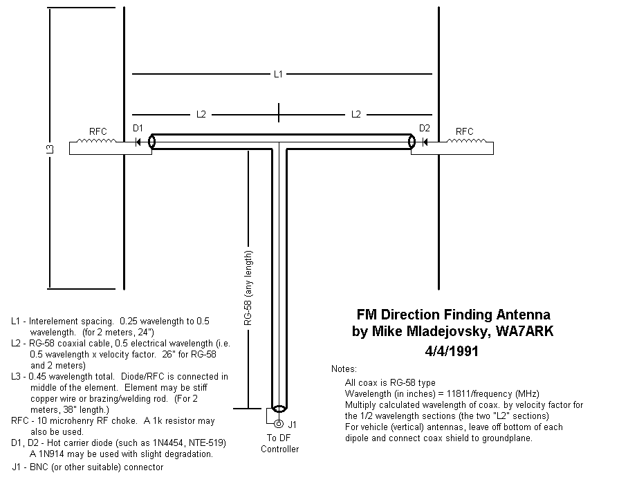
J2 - To this is connected the antenna array mentioned above. This connector can be any sort suitable for the frequency involved: For 2 meters, a BNC connector is typically used.
J3 - To this is connected
the receiver and the comments about connector type for J2 also
apply. Make sure that you clearly label the two connectors
as the unit will not work (but will not be damaged) if they are
inadvertently swapped.
J4 - Audio is input from
the receiver via this connector: A stereo jack is shown, but
this could also be a simple cable with a hardwired plug to match
the receiver that you plan to use.
B1 - This circuit can be
operated from any voltage from about 6.5 to 20 volts, but for
portability a 9 volt transistor-type battery is typically
used. Note the presence of D1,
a 1N4001 (or practically any diode capable of at least 1
amp): This prevents U2 and/or U1 from being damaged should
reverse-polarity accidentally be applied - something easy to do
momentarily if one is trying to attach a 9 volt battery in the
dark!
SW1 - This is a simple
on/off switch for power.
PB1 - This is a
normally-open pushbutton switch. This is used to initiate a
calibrate sequence that allows the microcontroller to adapt to the
characteristics of the radio being used.
LED1A, LED1B - This could
be one or two LEDs. In the prototype in Figure 1, a single
"dual-color" LED was used with one color (Red) indicating right
and the other color (Green) indicating left. If so-desired,
separate LEDs could be used (as
shown in Figure 3) to do the same function and their
location (left or right) could also indicate the apparent
direction of the signal.
LED2 - This is a single
LED (optional) used to indicate the status
of the unit in "Version 1" only. This is primarily used to
indicate an overload condition due to excessive audio input
levels. You may wish to choose to omit this LED. This part was omitted in Version 2.
M1 - This is an optional
meter that can be a method of indicating direction. Often,
surplus "Zero-Center" meters can be found and one of these may be
used to provide a left/right indication. This could be used
in addition to the LED or instead of it. Variable resistor R9 is used to set the
"maximum" reading of the meter. Note:
It
is
possible
that
a standard non-zero-centered meter could also be used - contact
the author for more details.
Additional information for
the Version 2 circuit:
D2 - This is used to detect field strength via the antenna. For best sensitivity, use a germanium diode (such as a 1N34) or a microwave Schottky diode (e.g. HP2835 or similar.) A small-signal silicon diode (such as a 1N914 or 1N4148) may also be used, but its use results in significantly lower sensitivity! It may also be possible to use an active RF detector such as a logarithmic amplifier (see below) or a simple RF amplifier in front of the detector diode.
SW2 - This should be a center-off SPDT switch if one
wishes to have a "TDOA-Only" mode available (recommended!)
 |
 |
Additional comments:
For the "Version 2" some changes were made and these include:
Note: Those changes
marked with an asterisk (*) may be applied to the Version 1
schematic as well.
Building the unit:
As can be seen from the pictures, this unit was built into a
piece of prototype perforated board: While a printed circuit
board could easily be designed, this has not been done.
Most aspects of construction are not critical, although there is
the obvious recommendation of using an 8-pin socket for the PIC
and to be neat in wiring as much as practical. What is
rather critical is the wiring of the components associated with J2 and J3, the antenna and receiver
jacks!
Figure 3 shows the
prototype after having been repackaged in an enclosure. The
enclosure (A Serpac M/N: H-67, 9V which is Digi-Key
P/N: SRH67-9VG-ND) contains a separate compartment for 9
volt batteries and comes with spring contacts. The power
switch, speaker, LEDs and BNC connectors were held in place using
either epoxy glue and/or rubber adhesive.
A small speaker was installed and a disconnect-type 3.5mm stereo audio jack (just visible on the lower-left) to allow the use of headphones: The jack was wired so that the left channel contains only the tone while the right channel contains the audio from the receiver.
For this enclosure, separate left (green) and right (red) LEDs
were used and I chose not to implement the "Overload" LED, as the
volume required to make it illuminate is rather deafening!
A pair of BNC connectors for connection to the radio and antenna
array may be seen along the right side of the enclosure and the
"Calibrate/Mode" A pushbutton switch can be seen along the left
side, just above the speaker: Most of the "button" portion
was removed, making an accidental operation less likely and to
reduce the probability of the button snagging and being broken
off. The power switch can just be seen protruding from the
lower-right side.
The Antenna and Radio Jacks:
As can be seen from the the bottom photograph of Figure 3, there are some
components wired directly to J2 and J3
- namely C4 and R4 and, for Version 2, C9, R11, D2 and C10.
The important point to be made here is to minimize
lead length!
Keep in mind that at J2 and J3 we have the RF from our antenna and
it is best to keep very short (centimeter) lead lengths to
minimize signal losses and to prevent stray pickup.
J2 and J3 have been purposely placed very close to each other,
and in so-doing, the ground (shield) connections of these two
jacks are connected to each other with a short wire and the
various components may be soldered directly to these points.
There are a total of three connections made to the J2 and J3
circuit, namely a DC ground, the antenna drive signal from C3,
and, in the case of the version 2 circuit, the connection from
D2/C10.
Operational notes:
STARTUP:
DISABLE YOUR RADIO'S TRANSMITTER!
First, disable the
transmit function if you are using a transceiver!
If your radio doesn't allow this, set it to the lowest power and
take care to avoid accidentally transmitting and destroying the
antenna switching diodes and/or D2. This is important
enough to say twice!
When the unit is powered up, the OVERLOAD indicator (Version 1
only) and one of the Left/Right LEDs will light for about a second
and the antenna switching frequency will change several times,
indicating that the unit is restarting. At this time,
the unit will load the stored calibration, if one was
present. Note that the packaged prototype shown in Figure
3 does not include the "Overload" LED: This is because
most Handie-Talkies simply cannot output enough audio to overdrive
the input of the TDOA unit, so there was no real need to install
it - plus this LED isn't used with "Version 2" firmware anyway.
CALIBRATION:
Before anything else is done, the unit MUST be calibrated to the specific radio being
used. This is done by tuning in a strong, stable, UNMODULATED carrier and
adjusting the antenna array for the loudest, cleanest tone (the
two elements of the antenna array inline with the signal source,
as if it were a Yagi) and then pressing the CALIBRATE button for
about a second. Once the pitch of the tone changes, release
the CALIBRATE button - but keep the antenna steady until
calibration is complete!
Once calibration has started, a low-pitch tone is heard and once
it is complete (it takes about 3 seconds) the unit will restart as
indicated by the changing audible tones.
Note: Avoid accidentally pressing the calibration button! In later firmware (e.g. Version 2) a button-press of about a second is required to initiate a calibration sequence, although brief "accidental" presses of the button will cause the unit to "freeze" for an instant (with the unit immediately returning to normal operation) as the button-press is being timed.
The calibration information is stored in non-volatile memory in
the processor and unless a different radio is
used it need not be done again. There is, however, no harm
in recalibrating the unit every time you use it.
Important notes about
calibration:
LED Brightness:
The brightness of the direction LEDs is related to the loudness
of the received tone: The stronger the tone (or, the farther
off-point the antenna) the brighter the LEDs and/or greater the
meter deflection. When the unit is calibrated, the loudness
of the tone at the time of calibration is taken to be the level of
"full" brightness. This means that if the volume is later
increased, it won't "dim" as easily when the antenna is
aimed. Conversely, if the volume is later reduced, the LEDs
will be dimmer.
If, for whatever reason, you want the LEDs to run at full
brightness all of the time, simply perform the calibration with
the radio's volume set very low - but just high enough to get a
reading. In this way when the volume is increased, the LED
will be correspondingly brighter to match the audio.
LED Response to signals:
Antenna nulls:
If there is sufficient "switching tone" in the received audio,
either the "Left" or "Right" LED will be illuminated. Note,
however, that is the antenna is aimed exactly at the signal source
(and there is no multipath present) that the switching tone will
null out (disappear) from the speaker audio: This is a
normal behavior for TDOA antenna sets and this is, in fact, an
additional audio cue that your antenna is aimed.
When the tone disappears into a normal antenna null, the
TDOA unit may not have sufficient signal to detect the switching
tone. When this happens, BOTH the left and
right LEDs will illuminate and the switching tone will seek a
"middle" frequency.
Remember:
The effects of signal modulation:
When the signal is modulated, the switching tone - which is used
to determine the signal bearing - gets mixed in with that audio
being modulated. This can "dilute" the switching tone and
make it harder to detect by the TDOA unit in addition to making it
more difficult to hear by the user!
To reduce the effects of such "dilution" the TDOA unit applies
several filtering techniques to recover the "buried" switching
tone. Nevertheless, expect the Left/Right indications (both
the tone and LEDs) to be affected by such on-channel audio.
What usually happens is that the unit becomes a bit slower to
respond to left/right indications, and the left/right LEDs may
randomly flicker with the modulated audio. In general,
however, one can easily spot which left/right LED is on most of
the time, despite the flickering.
The effects of modulation on the receive signal are most severe
when the antenna is aimed in the direction of the signal and a
null in the tone occurs. Because the switching tone will
naturally null out anyway, it becomes harder to detect and the
left/right indications (either via LED or tone) become
less-distinct. It is these situations that teach one the
value of constantly sweeping the antenna back-and-forth as one
walks: Moving the antenna off to the side causes the tone
amplitude to increase, allowing one to hear it and judge where the
"center" would be if one could hear it!
In most cases, the TDOA unit can actually detect the switching
tone more readily than one's ear. It is for this reason
that, through the headphone jack, one can hear only
the switching tone and no receive audio on one of
the audio channels. With this, one can still hear the
switching tone's frequency even if it is too weak to hear with the
"naked ear" and it allows the tone to remain audible even if there
is a lot of on-channel modulation!
Comments about the antenna array
and switching tone:
The use of different
radios:
If you use several different radios, please be aware that the
unit will have to be re-calibrated each time you change radios!
Also be aware that some radios may have "inverted" audio phase as
compared to others. This can cause the Left/Right indicators
to become reversed: For this reason, re-check to verify that
your "left-right" indication is correct. Simply reverse or
turn the array upside-down to correct this!.
Changing frequency range:
This unit has two tone-variable frequency ranges and two
fixed-frequency modes available in the TDOA mode:
Approximately 400-525 Hz (the default) for the "low" variable-tone
range, or about 640-770 Hz for the "upper" variable-tone
range. In the "Fixed Frequency" mode, the low range's tone
is approximately 475 Hz while its high range is about 700 Hz.
The range of tone frequencies may be switched by holding the
CALIBRATE button down for about 10-12 seconds. After holding
it down for about 4 seconds, the unit will "diddle" quickly and do
a calibration and then restart as indicated by the OVERLOAD LED
lighting up. After this, continue to hold
the CALIBRATE button and after another 3-4 seconds, tone will
"diddle" again, but more slowly. Continue holding the
button until after the "diddle" stops and the frequency
range of the switching tone will switch from low to high or
vice-versa and at this time the button may be released. This
selected mode will be saved in EEPROM.
The various tone modes are accessed sequentially, as in:
The "Fixed Frequency" modes, as you may have already guessed, are those in which the tone does not change frequency with respect to relative bearing so this means that if you are using this mode, you will have to depend on audibly detecting the null of the tone as well as looking at the indicator LEDs (or meter, if you've included it) for a "left/right" indication. The fixed frequency modes were added to help deal with those situations where the signal being receive is being very strongly modulated - particularly with a tone - that might tend to confuse the circuit and cause false left/right indications or, at the very least, "dilute" them with noise. While it is usually possible to deal with this situation by appropriately selecting the low or high variable tone range, having a "fixed" tone range with the frequency selected to be as "far as possible" from that which is being modulated on the signal may be of help.Low Variable (400-515 Hz) -> High Variable (640-770 Hz) -> Low Fixed (475 Hz) -> High Fixed (700 Hz) -> and back to Low Variable
The "Overload" LED (Version 1
only):
Remember: Not all
radios can output enough audio to cause the CLIP LED to
illuminate! The OVERLOAD LED does NOT indicate whether or
not the audio output from the radio itself is distorting! If
the OVERLOAD LED indicates, turn down the volume slightly.
On most radios, volume settings should not affect calibration,
unless the calibration was done with the volume high enough to
cause the radio's audio amplifier to clip. The
"OVERLOAD" LED is not implemented in the "Version 2" (field-strength
meter) modes.
DISABLE YOUR RADIO'S TRANSMITTER!!!
If you are using a transceiver - such as a handie-talkie, you
should disable
the
transmitter if possible and if not, set it to the lowest
power. You should then calibrate the unit as described above
unless you know for absolute certain that you have already
calibrated it to the radio that you are using. (If you
aren't completely sure, re-calibrate!)
Again: If you do not know for certain that the unit has been calibrated with your radio, you should do so now! Failure to do so may cause poor performance and/or erroneous/misleading readings!
Then, the user should, with a known signal toward the front, verify proper operation of the unit by moving the antenna left and right, making sure that the tone goes up or down (and the LED goes red or green) with left or right movement of the antenna. Note that it is the user's preference that determines whether or not a "high" tone indicates that the signal is to the left or to the right. Note that if there is no audio input or if there is equal or conflicting phase information from each antenna, the "direction" LED(s) will flicker quickly between red and green.
NOTE: As with most
2-antenna TDOA units, proper LEFT or RIGHT indication depends
completely on two factors:
Users of this (or ANY) TDOA or other direction-finding system
should PRACTICE so that its operation becomes second nature.
ONLY if this is done will the user be able to get the "feel" of
how the unit responds to signals of various qualities.
Determining the signal bearing:
My personal preference, when looking for transmitters, is to
constantly sweep the antenna array back-and-forth,
as one might using a metal detector, while
one is walking or driving. When doing this, you
will note several things:
When using a system such as this, I rely almost entirely on the audible indications rather than looking at the unit's LEDs or front-panel meter: This is highly recommended, as it is important that you watch where you are going, keeping an eye out for obstacles, traffic, or even the transmitter itself! Above all, be safe!
If you have immediate interest in this, you may send email - follow this link.
Pre-Programmed PIC for this project:
Related Links:
This page updated on 20130304