On the workbench: A barely-working 10 GHz-to-70cm transverter.
Click on picture for a larger version.
|
This is page was been quickly thrown together as a place to stick some pictures and descriptions of this 10 GHz transverter and other 10 GHz-related activity.
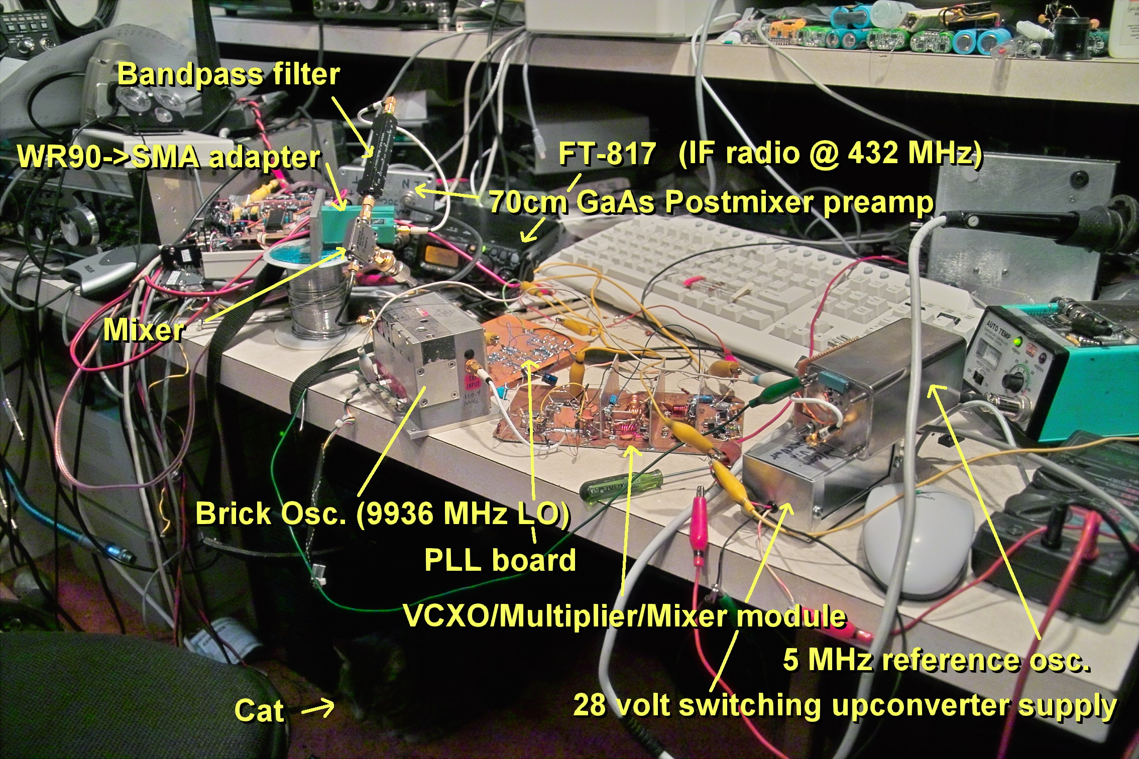
This is a semi-homebrew transverter that converts 10 GHz down to a fixed IF in the 70cm band.
Actually, its IF is not "fixed" at all: It could practically be anything from a few MHz to 1 GHz, but with the local oscillator at 9936 MHz, the weak-signal calling frequency of 10368.0 gets converted to 432.0 MHz and the entire 10 GHz amateur band itself goes from 64 to 564 MHz on the IF, but bandpass filtering limits the practical range from about 10050 to 10500. This also means that a simple WFM/NBFM exciter/receiver could be built that operates at 314/344 MHz (to transmit/receive at the FM frequencies of 10250/10280 respectively) and take advantage of the relatively low IF for frequency stability.
Shown in Figure 1 is the transverter, on the workbench, being tested with a Yaesu FT-817 tuned to 70cm.
Interested in schematics/details of the various blocks? Go to the Schematic/Explanation page.
How well does all of this work? At the time that the photograph at the top of the page was taken it barely worked for several reasons:
 |
This picture shows the various modules screwed down to a piece of plywood as shown in Figure 2. This, while not pretty, at least made it possible to transport the unit around so that it could be used for the microwave contest held on the 22nd and 23nd of January, 2005. All that was required to make this work was to apply 12 volts (from a battery) and allow the ovenized oscillator to stabilize, and then use the 70cm IF radio to transmit/receive.
A few details about the transverter, in its current state:
 |
A really simple 10 GHz signal source:
Did it work in the state shown in Figure 1? Yes, it seemed to, once the appropriate incantations and genuflections were done to make everything lock.
Not being able to hear the 10 GHz beacon (I was inside, in the basement, using just an SMA to WR-90 adapter flange for an antenna, not using a GaAsFET preamp - and I didn't know for certain that the beacon's even running at that moment...) I needed a 10 GHz signal source. Initially, I thought about trying to receive weak harmonics radiating from the 110.4 MHz multiplier - but a quick check with a calculator showed that they happened to end up in the same place on the converted 3cm frequencies as they did at the 70cm IF.
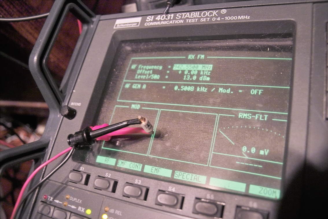
The (successful) attempt is what you see in the picture: A
microwave
mixer diode connected, with a set of EZ hooks, to the output of
the
service
monitor and the diode placed near the open end of the waveguide
adapter
(I observed that polarization of the diode mattered
greatly.) The
service monitor (and locked to the GPS reference) was tuned to
942.550
MHz and the output cranked up all the way to +13 dBm.
|
At the time that this transverter was constructed, the WA7GIE 10 GHz beacon operated on approximately 10368.120 MHz - plus/minus 5 to 10 kHz, depending on temperature and was horizontally polarized using a slot antenna and approximately 200 milliwatts of RF from atop Nelson Peak in the Oquirrh mountains. Keying is actually FSK-CW, with the "Key-Up" frequency being about 10 kHz higher than the "key down" frequency: This means that the transmitter is keyed continuously - a fact to remember if attempting to receive it using a wider IF (e.g. narrow or wideband FM.) Back then, the keying ws somewhat chirpy and the frequency tends to drift a few kHz with temperature. Click here to listen to a recording of Dave's beacon (.MP3 file, 160k.) The first portion of this recording contains an entire beacon cycle while the second portion is the "unkeyed" frequency (about 10 kHz up) with the "reversed" keying. The final portion was recorded in Narrow FM mode tuned midway between the two frequencies: The "clicking" is the shifting of the beacon frequency during keying. This recording was made with the transverter, using
a
17dbi horn,
sitting in my living room: The signal had to go
through walls,
trees,
and a neighbor's house. Since then, the WA7GIE beacon has been rebuilt using a
much more stable oven oscillator and a different keyer -
read more about it at the Reworking the
WA7GIE Beacon page. |
At this frequency, the 4-5 inches of wire that connect the EZ hooks at the ends of the coax (and the hooks themselves) are probably radiating most of the 942 MHz energy, but some of it is getting to the diode: An S-9 signal was registered on the S-meter of the FT-817. To convince myself that this signal really was on 10 GHz, I waved the diode back and forth and heard a +-100 Hz doppler shift as I did so.
The signal at 10368.05 (the 11th harmonic of 942.55) sounded somewhat ratty with incidental FM (although good enough for intelligibility on SSB) but I suspect that most of this is the service monitor which starts to sound just a tiny bit "warbly" on 70cm (an effect that would be 24 times worse at 10 gig) - and this is not to mention the possible effects of having low-level signal leads flying everywhere. The FT-817's display showed that 432.0503 (an error of 300 Hz) at zero-beat, but some of that was likely due to the fact that I'd brought the '817 in from the car not too long before.
Note: As it turns out, the 11th harmonic, direct from the service monitor, could be heard weakly if the EZ-clips were held right up to the waveguide flange: With the diode they were detectable from across the room... The harmonics of the service monitor itself (no diode) could be heard from several inches away, as could the higher-order harmonics from an HT on 70cm - and even on 2 meters! Note, however, that even narrowband modulation on 70cm becomes extremely wide when multiplied to 3cm!
The first 10 gig SSB contact:
Just after sunset, we (Ron and I) called it quits and headed down into the valley fog. Not too long after getting back onto the freeway, Dave, WA7GIE appeared on the 2 meter coordinating frequency, ready to try a 10 GHz SSB contact so I immediately headed back toward the site that I'd been at earlier that day (along U-111) but the fog had thickened such that visibility was only 100 feet at most - and I could not find my previous spot. Pulling over, I turned on my GPS receiver and used it to locate that spot - more or less - and set up in the dark about 100 feet off the side of the road.
Coordinating with Dave, we both tuned in the beacon (then, on about 10368.292 MHz) and noted our respective frequency displays and then QSY'd down several kHz with him calling first. With his 1 watt of RF and small dish pointed in my general direction, I immediately heard his signal very strongly and I peaked my horn antenna on his signal. Despite my 1.25 mW of EIRP he had absolutely no difficulty in hearing my signal. This occurred at about 7:15PM on a frequency of approximately 10368.288 MHz..
After several minutes of fiddling with peaking antennas, etc. we decided to try other modes as well, so we tried NBFM - but Dave could not hear me at all. We quickly realized that we were too close to his beacon frequency and QSY'd down to approximately 10368.275 and had absolutely perfect noise-free communications. We then switched to AM: He was able to hear me just fine and I was able to copy him OK, despite a possible misadjustment of his IF rig (also an FT-817: The factory settings for AM on the '817 radio have been known to be incorrect on some radios) that badly distorted his AM audio. We then switched back to SSB and shortly thereafter, concluded the QSO at about 7:22 PM.
To our knowledge, this is the first 10 GHz SSB QSO with both ends
in
Utah, and is most likely the first QSO of any kind (in Utah) on
10
GHz
using
AM.
(Note: A 10 GHz distance record was
set
in the early 90's using SSB with one of the two ends in
southwestern
Utah
near Cedar City.)
Go to the
KA7OEI
microwave page.
or
This page last updated 20131126
Since 12/2010: