
|
Sec. 15.219: Operation in the band 510-1705 kHz. (a) The total input power to the final radio frequency stage (exclusive of filament or heater power) shall not exceed 100 milliwatts. (b) The total length of the transmission line, antenna and ground lead (if used) shall not exceed 3 meters. (c) All emissions below 510 kHz or above 1705 kHz shall be attenuated at least 20 dB below the level of the unmodulated carrier. Determination of compliance with the 20 dB attenuation specification may be based on measurements at the intentional radiator's antenna output terminal unless the intentional radiator uses a permanently attached antenna, in which case compliance shall be demonstrated by measuring the radiated emissions. |
PSK31 and MedFER
operation
Version 2.0 of the PIC
code is now available!
This new version allows
messaging and control via a 1200 baud RS-232 port! See
Below for more info.
Notice: The "CT" beacon is currently running full-time in QRSS3 mode.
The beacon is being keyed by a simple controller based on the PIC16F275 8-pin microcontroller.
For request to change modes or for questions about the beacon or its controller, feel free to send an email.
I had seen references to, and heard mention of PSK31 for a year or so before the article appeared in the May, 1999 QST ("PSK31 - Has RTTY's Replacement Arrived?" pp. 41-44. 128K .PDF) This article intrigued me, as it seemed to be an evolution of the BPSK experimentation that I had done a dozen years before (Check out the CT LowFER Archive page.) It wasn't until August, 1999 that I finally went to the Official PSK31 Site and downloaded the windows-based PSK31 software and other documentation at the site.
PSK31 seemed to be a natural for MedFER and LowFER beacon operation, but there didn't appear to be any way to generate it that wouldn't tie up an entire computer and SSB transmitter. It didn't look as though it would be too difficult to implement, so I set about building a PIC-based PSK31 (or FSK31) exciter (refer to the links at the bottom of the page for more details.).
The station:
Note: Click on any picture to get a bigger version
|
My house is modest sized 2-story located on a fairly small lot. While it would be possible to have put the MedFER antenna in the yard (on the ground) I put it on the roof for three reasons:
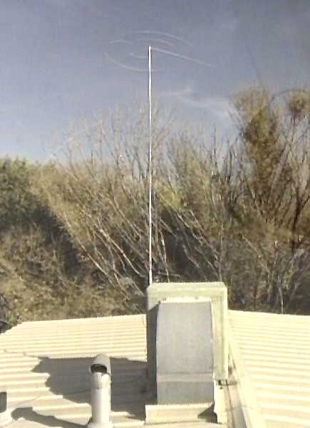 |
The rules specify that the antenna length (plus ground lead) may not exceed 3 meters (about 9 feet, 10 inches.) In this particular case, the transmitter itself is located a bit less than a meter from the base of the mast: Don't forget that the portion below the transmitter radiates, too, as it has current flowing in it, and is therefore part of the 3 meter measurement.
The rules in Part 15 don't actually describe the antenna itself. Some people take an extremely conservative approach and use only 3 meters of conductor in the antenna. Others (myself included) feel that a 3 meter, tophatted vertical falls within the rules. The tophat increases the capacitance of the antenna, allowing a reduction in the amount of inductance needed to resonate the antenna, and thereby reduces coil losses.
 |
Second only to ground losses (at least in this system,) matching
losses
factor largely in the efficiency of this vertical antenna system.
The transmitter is not designed to match only to 50 ohms but to
the feedpoint resistance of the antenna once the reactive component has
been canceled out. The antenna itself (with its new capacity hat)
has a capacitance of about 83 pf, so it takes roughly 105 uH to bring
the
antenna to resonance at the operating frequency (approx. 1705
kHz.)
 |
If everything were perfect, the system feedpoint resistance would be exactly that of the antenna - but things are not perfect: The real system feedpoint resistance is the sum of the antenna's feedpoint resistance plus ground losses plus coil losses plus other losses (such as dielectric losses, etc.) In real life, the resistances of these additional losses are much greater than the feedpoint resistance of the antenna and greatly reduce its efficiency.
The Transmitter:
The "AM" version of the transmitter (described in more detail here) is rather unique. It uses a simple PIC (microcontroller) to generate the PSK31 varicode and modulation - but it uses a highly efficient non-linear RF power amplifier (nominally Class-E) to generate the RF.
Now, anyone familiar with PSK31 knows how important it is to make sure that your transmitter is linear - lest your signal splatters up and down the band (something that good amateur operation practice definitely frowns upon...) so how is a PSK31 signal generated with non-linear amplification? The answer: By separately modulating the amplitude and phase.
Modulation of the PSK31 signal simply requires that the amplitude be (gracefully) brought to zero before a phase transition occurs - and then be (gracefully) brought back up again. The phase shift is easy to accomplish - just an XOR gate (or equivalent.) The amplitude isn't that hard either: Just vary the supply voltage to the power amplifier in an appropriate manner. In this transmitter the PIC does this by synthesizing the modulation waveform voltage (1/2 a sine wave) by using PWM (Pulse Width Modulation) techniques instead of using a D/A converter - followed by appropriate filtering and amplification. Ultimately, the power amplifier is modulated by using a simple emitter-follower tacked onto an op-amp section. In the simplest sense, this modulation scheme somewhat resembles the HELAPS (High Efficiency Linear Amplification using Parametric Synthesis) scheme devised originally by AMSAT for use on the OSCAR spacecraft (although I'd not heard of HELAPS at that time) where the highest power efficiency was required. While it wasn't required that power consumption be absolutely minimized, it was convenient to use an efficient and simple means of generating the RF.
The loading coil:
The present loading is the second one to be used for the beacon, with the previous loading coil having been wound with two parallel strands of 10/40 Litz wire. This wire is best used on LowFER frequencies (about 175 Hz) and was left over from a previous LowFER transmitter. While this wire was not optimal for use at 1.7 MHz, it was better than single-strand wire at the frequency. As it turns out, Litz using #48 (AWG) wire (such as 100/48) is that which is best for this frequency, but not having a ready source for any, I resorted to what was available at the local hardware store.
Instead of litz wire, I decided to use something else that has
a
large surface area (to minimize the "skin effect" - the tendency for an
A.C. current to flow on the surface of a conductor rather than along
its
entire cross-section) - some 1/4 inch diameter soft copper
tubing.
Copper tubing was chosen because it is (relatively) cheap ($10-$15 for
a 50 foot coil) and readily available. Because of the
skin-effect,
it would not make sense to use solid wire (which is scarcer and
probably
much more expensive, not to mention much heavier and harder to work
with.)
The disadvantage of using such a large coil is that more conductor is
required
to obtain the required inductance - owing to the large size. Any
plans for future improvements? Maybe later...
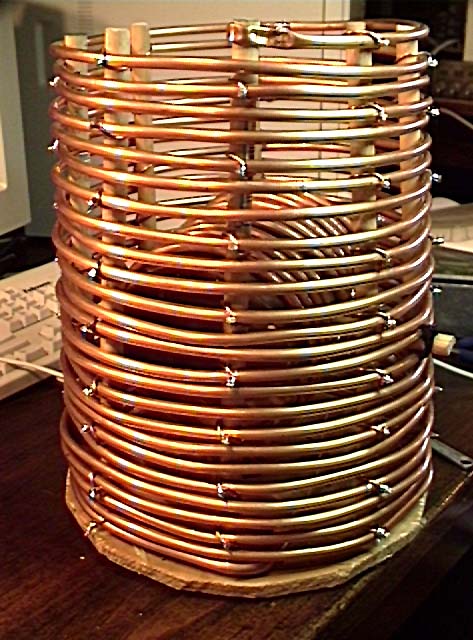 |
The coil form is constructed using a base of plywood. 8 holes were drilled in it to receive 1/2 inch wooden dowels which were glued into place. The tubing (approximately 65 feet (approx. 20 meters) was wound on the form. #12 and #14 wire is used to secure the tubing to the form in a systematic fashion. (If I'd been paying attention, I would have used an odd number of dowels so that the turns could have been "basket-woven" to reduce the capacitance between windings of the coil.)
For adjustment of inductance, a variometer was needed. Additional turns of tubing were wound on a piece of thick cardboard and a piece of dowel material was used to mount the variometer. After construction, all pieces of wood and cardboard were liberally slathered with varnish to make them more resistant to moisture. An inverted plastic bucket is used to protect the coil from the weather and the wooden base of the coil is bolted to the "bottom" of the bucket. To maintain spacing between turns (and prevent possible shorting) the turns were secured/insulated with clear RTV (silicone) as appropriate. As it turns out, dry cardboard isn't very lossy at 1.7 MHz, hence the form was more than adequate.
Initially, I noticed that I didn't have quite enough inductance to resonate the antenna so a small bit of ferrite was added to the variometer to make up the difference. Even with a bit of lossy ferrite. What was the result? The antenna current increased from about 20 milliamps average to about 40 milliamps average (PSK31 has a significant AM component, remember.) This corresponds to an approximate 6db increase in radiated power.
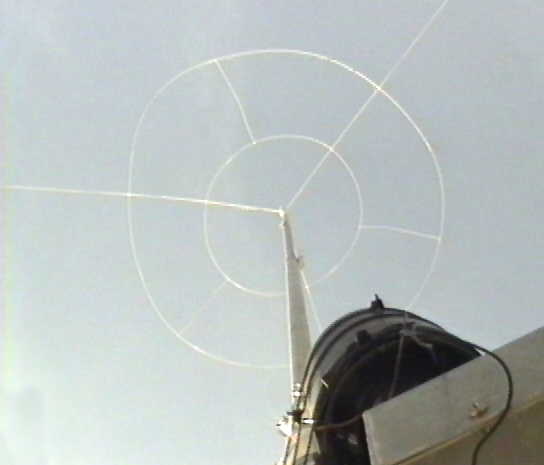
On 3 February, 2001 I upgraded the antenna on the MedFER beacon: I stripped off all of the old tophad "rings" (they were just painted piano wire) and replaced them with three #14 copperweld (tm) rings, added three more "spars" on the tophat made from #10 copperweld, and added 6 "cross-connects" that connect the rings in their midpoints, mechanically stabilizes the tophat and increases capacitance even more. Prior to the "tophat rebuild" it took about 143 uH to resonate the antenna and now it takes just 105 uH - implying an antenna system capacitance increase from about 61 pf to approximately 83 pf.
This added capacitance also allowed me to remove the last little bit
of ferrite in the variometer. I also had to readjust the tap on
the
P.A. to a lower impedance, indicating that the system's resistive
losses
are lower. An increase in antenna current to about 65 milliamps
average
was noted, indicating that radiated power was likely increased. (Note:
I
recently
checked
the calibration of the RF thermocouple ammeter at DC
and found it to read high by almost 50%, so the antenna current
readings
mentioned in previous paragraphs have been corrected appropriately.)
 |
Note that the antenna system resistance (which will not be 50 ohms on an electrically-short antenna such as this) must be matched to the transmitter. In the case of this transmitter, the inductor in the output stage is tapped, providing several impedances to select from. If there are several taps, one of them is likely to be pretty close to the correct impedance.
The base of the vertical antenna is insulated from the grounded
portion
and it is to this that a weather-resistant enclosure containing the
transmitter
is mounted. There is a static protection network on the
transmitter
output (barely visible in the picture, just above the upper-left corner
of the circuit board, consisting of a neon light and a bleeder
resistor)
to protect the transmitter from static discharge and nearby lightning
strikes.
Additionally, the DC power input is protected/filtered with inductors
and
capacitors.
Knowing the drain impedance of the amplifier and the tap position on the transmotter's output autotransformer I have calculated the feedpoint resistance of the antenna system to be between 15 and 20 ohms. I have also measured the feedpoint resistance twice with difference pieces of test gear - once with a Heathkit RX noise bridge and another time with an AMQRP AA-908 antenna analyzer and both of these devices have also shown the feedpoint resistance to be on the order of 15 ohms, so I'm pretty confident that it's correct!
How well does the
beacon
get out?
 |
The beacon has been installed and has was running perfectly since October 1999 having survived wind, rain, snow, and lightning - running continuously (except during LF and MF listening sessions, and those times during which I forget to turn the beacon back on after a listening session...) Reception reports indicate that the beacon can be heard with only modest HF antennas anywhere within a 35 mile (56 km) radius. The beacon is also intermittently copiable at a distance of 75 miles (120 km) over multiple mountain ranges during daylight hours (see the screen display.) At this distance, the signal fades in and out, probably due to multipath effects between the skywave and groundwave.
On 24 March, 2001, Steve, VE7SL was able to copy the beacon when it
was in the QRSS (three second dit) mode from the Puget Sound area (a
distance
of about 800 miles, or 1300 km.) Since that time, Steve has
copied
the beacon numerous times via QRSS. More information about QRSS (Slow
CW) may be found here.
How has the beacon held up over the years?
Since its installation in October of 1999, the beacon has been on
the roof continuously. The most maintenance-prone portion of the
beacon system is the loading coil's cover. This cover - which
originally was just an inverted, blue polyethylene
plastic bucket, had been in the sun for several years and made
extremely
brittle by Ultraviolet radiation. The jostling of the antenna by
the wind finally shattered a portion of the bucket, and the coil had to
be removed for safe keeping. Due to time constraints (and the
fact
that it was outside the prime "MedFER" season) it wasn't until mid-July
that the beacon was returned to operation. Since that time,
several more buckets have been used, each lasting 3-5 years.
As for electrical operation: Nothing has gone wrong with the
beacon
at all since day one - this, despite plenty of wind, rain, weather and
thunderstorms!
The coil has held up well, needing only to replace the bucket every
couple of years when it deteriorates due to ultraviolet exposure and
with a few parts of the coil needing the occasional re-gluing and
touch-up with silicone.
The only problem that I have experienced with it is that if the
beacon is off for more than a few days during warm weather, hornets
will start building a nest, causing the system to be badly detuned when
it is turned back on and the need to carry out a very careful "hornet
eviction."
For some reason they don't build a nest in the coil it when
there is RF... Hmmm...
Transmitter
modifications:
Since this transmitter was first installed, it has been modified somewhat: Capabilities were added for Amplitude Modulation (which happens on 1700 Hz, switching to a different crystal with a relay) as well as a means by which the PSK31 modulation may be disabled, allowing CW keying. Why aren't these modifications on the schematic? The basic PSK31 transmitter is unchanged, and the modifications are fairly straightforward.
How, then, is QRSS done? Extra lines were used to disable the PSK31 keying and allow straight CW keying (by directly controlling the modulator - the PIC is still blissfully generating PSK31 - but it isn't going anyware...)
Take a look at these other pages at this site:
Updated (With software version 2.0x) - Circuit and software description of the PIC-based PSK31 MedFER Transmitter. (Note that FSK31 operation is also possible!) - Operation via a 1200 baud serial port is now possible, and the intermod has been greatly reduced!
"Optimizing the 'Simple Beacon' Transmitter" by Mark Mallory - This article originally appeared in the Western Update (#59, September, 1988). This is the original article describing a high-efficiency Class-E LowFER transmitter.
The "CT" LowFER Beacon Archive - Some pictures/info about the "CT" LowFER beacon of the late 1980's. (Includes QSLs and sounds from some other beacons of the time.)
A Line-Synchronous noise blanker for VLF/LF/MF use - This blanker produces very little intermod, compared to many others...
"QRSS and You..." - Using absurdly low-speed CW for "communications"
Using your computer to ambush unsuspecting NDBs - A brief description of how Spectran may be used when trying to receive NDBs.
The KA7OEI FT-817 pages - This collection of pages describes in some detail the inner-workings of the FT-817, as well as various things that can be done to improve the performance of the transceiver.
Restoring my Atwater Kent Model 20 Compact receiver - This page describes how I restored an old Atwater Kent Model 20-C receiver to operating condition - and how it was used for NDB reception!
For even more information, check these sites:
A good PSK31-related link:
The
PSK31 "Official Homepage" - Has articles, software, links to other
pages and many of the available PSK31 programs.
DSP Software for digging out the weak/buried signals (These are definitely worth getting!):
Spectran Beta 4 and ARGO
- Spectran is the successor to the well-known Hamview program. It
is currently in beta-test. This windows version can use any
standard
(full-duplex) sound card. Like "Spectrogram" this program produces a
graphical
"waterfall" display and has a real-time audio bandpass filter.
This
program is more specifically suited for amateur/radio use as it's
display
algorithm can more distinctly show "buried" signals than
Spectrogram.
It's frequency range is limited to audio, however. The ARGO program is
specifically tailored for QRSS - extremely slow speed CW. (By
I2PHD
and IK2CZL. Freeware.) You can download these from the Weak
Signals web site.
Spectrum Lab - by DL4YHF. This is a very versatile program, frequently updated, that can be made to do a large variety of things and has a fairly steep learning curve. Making it display signals on a waterfall, however, isn't too hard to do!
Any comments or questions? Send an email!
This page maintained by Clint Turner, KA7OEI
and
was last updated on 20110606. (Copyright 1999-2011 by Clint
Turner)