Click on image for a larger version.
|
It was noted that this particular user ID is no longer to be found on Ebay, so this means that products of this quality will have to be obtained from other sources. It is possible that the user simply created another ID and continues to sell pieces of similar quality.
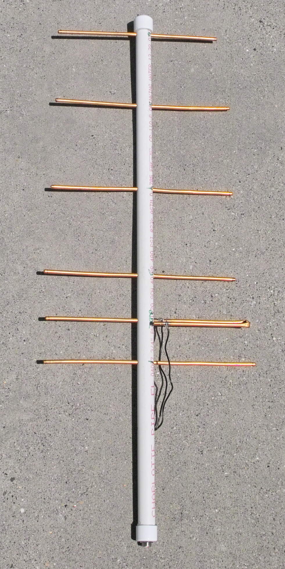
Several years ago a friend of mine bought four of these "440 Yagi Beam Antenna" as sold on Ebay by "Electronicsales425" for approximately $22 each and upon receipt of these antennas, he could not say enough good things about them. He also inferred that no price would be too high for an antenna of this quality!
Being impressed by them in this manner, he asked
me to take a look at them - and I must say that they are like no
antenna that I have seen before.
This antenna has a number of interesting features, including:
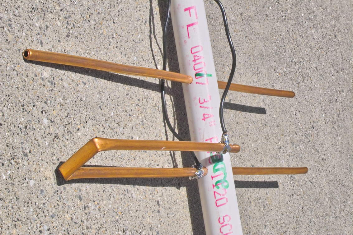 The unique "J-shaped" driven element. Note how the two wires comprising the "open-wire" feedline attach to the driven element. Without a matching network, there's little fear of it detuning due to rain, snow or ice! Click on image for larger version. |
 The unique "J-shaped" driven element and the open-wire feedline. Observe how the two strands comprising the open-wire feedline are cleverly routed into the boom. Click on image for larger version. |
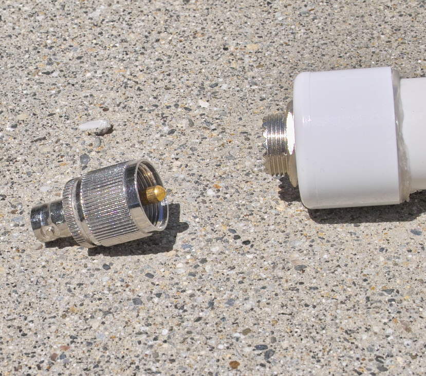 The end-mounted UHF connector. The open-wire feed connects to this single-hole UHF connector. As you can see, the use of this style of UHF connector and the relatively thick wall of the ABS cap takes up most of the threads of the UHF connector - as evidenced by the the connector to the left showing the comparison. As I'm sure that you'll agree, this lesser amount of exposed threads prevents one from being able to screw the connector on all of the way an "bottoming out" the connector and thus it may reduce the likelihood of the threads galling and being unable to remove connector the antenna. Click on image for larger version. |
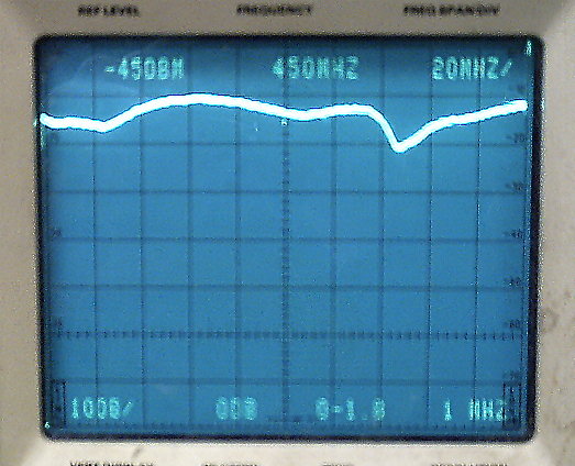 The return loss of the antenna, centered at 450 MHz. This shows the return loss from 350 MHz to 550 MHz with no more than 5 db of return loss at 450 MHz! As you can see, excessive return loss is no problem over the "440 Band" range for which this antenna was designed! When the 3 foot coaxial cable jumper was removed and the antenna was connected with a barrel to the directional coupler, the return loss was less than 2db! (Major horizontal divisions are 20 MHz and major vertical divisions are 10 db, with the "zero" line being the major division below the frequency readout.) |
As you can see from the quality of the construction and design
of this specimen, it is likely that no antenna
will perform as well as this one does and that this antenna cannot
be recommended too highly!
It need not be said how lucky you would be to get
an antenna such as this to work well for you!
Other online recommendations for this antenna:
P.S. I have no pecuniary interest in this antenna or its
seller. I have offered what I believed to be a fair
opinion based on the evaluation of one of four
identically-constructed units from the seller's production.
For other information, refer to the Lexicon of Inconspicuously Ambiguous Recommendations and related pages. (See also: This book.)
Click here for a few
antenna tips.
20190923