A temperature-stabilized 10 and 24 GHz Gunn transceiver system:
 

Front-panel view of the Gunn controller
Figure 1:
Front-panel view of the Gunn controller.  On the left is a rotary encoder to adjust the frequency while the IF receiver's volume and tuning controls are on the right.  The LCD shows the target frequency, the measured Gunn temperature, the tuning voltage and the battery voltage.

Click on picture for a larger version.


Temperature stability and Gunn oscillators:

One popular means of getting on the upper microwave bands such as 10 and 24 GHz is with the use of a Gunn transceiver.  These are free-running, cavity-tuned oscillators that typically produce 5-15 milliwatts (although higher-power units exist) and are typically modulated using wideband FM.

These devices are typically full-duplex - that is, they can receive at the same time that they transmit - a feat made possible by virtue of the fact that the transmit oscillator is also used as the local oscillator and a built-in mixer diode produces an IF signal that can be fed to a receiver for demodulation.  Since it is necessary to have this "other" receiver tuned some distance away frequency-wise, a "split" is used:  Traditionally,  amateur radio operators have settled on this "split" as being 30 MHz which means that when two people are talking to each other, their transmit and receive frequencies are 30 MHz apart from each other.

Because Gunn oscillators are free-running they are prone to temperature drift due to mechanical changes in the resonant cavity, changes of the operating characteristics of the Gunn diode itself, and changes in other circuitry such as the tuning varactor - if it exists and variations in the regulated supply voltage(s) - just to name a few.  To mitigate this, wideband FM (e.g. +/- 75kHz deviation of the sort used for FM broadcasting) is typically used as the relatively wide bandwidth of the receivers (around 300 kHz or so) can tolerate a bit of frequency error.  Even so, it is common for operators to have to chase each other around a bit as their individual Gunn units warm up or as their local weather conditions change and the temperature of the oscillators change with it!

Traditionally, several methods of dealing with frequency drift have been used with Gunn oscillators:
Having built a Gunn transceiver and being affected by drift, I decided to do something about it - but I decided on an approach different from any of the above:  Monitor the Gunn temperature and then apply corrections to keep it on-frequency!

How to tame your Gunn:

There are four major factors that will affect the operating frequency of a Gunn oscillator:

So, how about keeping a Gunn oscillator on frequency?

Right away, we can discard Gunn voltage simply by holding it steady with a reasonable-quality voltage regulator and removing it from the equation.  That leaves us just three interactive variables, namely Temperature, Tuning voltage and Frequency, all being related to each other in some way...

Let us take a quick look at math again and consider a generic linear equation with three variables:

Z = ax + by + c

and now let's rewrite it a bit, renaming the variables for our convenience:

F = xT + yV + z

Where:

F = Gunn Oscillator Frequency
T = Gunn temperature
V = Tuning voltage
x, y and z = Coefficients that we need to calculate!

How about higher-order functions?

As noted, the Frequency/Temperature/Tuning voltage relationships, when plotted out, describe a curve and not a straight line.  Because of this, a better equation would be something like:

F = a2T + xT + b2V + yV + c

These would be able to better-accommodate the curve of the tuning voltage and temperature effects on the Gunn frequency - but there's a problem:  This matrix turns out to require double-precision floating point or 64-bit integer math in order to solve with any useful degree of accuracy and doing either one would be a bit of a hassle (but not impossible!) on an embedded processor such as a PIC.

After realizing the difficulty with the above equation I decided to try a straight-line approximation - and it seemed to work out just fine for my purposes!


The above equation represents "straight line" approximations of the relationships between Gunn frequency, tuning voltage and temperature.

In actuality, when plotted out against each other the result is a curved line implying higher-order functions, but over a limited portion of that curve we will assume that a straight line will be "good enough." 

If we can determine the values of x, y and z, above, we can then simply plug those in and rewrite our equation as necessary to solve for whatever we need.  For example, if we know the temperature and the desired operating frequency, we can use the following equation:

V = (F - xT - z)/y

Which gives us the tuning voltage.  The trick now is to determine our values of the coefficients x, y and z!

How do we determine these?  The easiest way is to solve three simultaneous equations to calculate x, y and z with a 3x3 matrix, yielding these coefficients - but what do we plug in?

The easiest way to do this is to measure the Gunn temperature, Gunn Frequency and Tuning voltage under three different conditions, such as "Hot" and on frequency "A", "warm" on frequency "B" and then "cold" on frequency "C".  These readings are then run through the matrix to calculate the three coefficients which may then be applied to the above equation to determine the proper tuning voltage.

Actual Implementation:

The processor:

The PIC that I chose is the PIC18F2620, a 28 pin "high end" 8 bit processor with a multiplexed 10-bit A/D converter as well as two 10-bit PWM outputs - and it is one of these PWM outputs that I use for generating the tuning voltage for the Gunn diode.

Using software dithering techniques and external op amps for filtering and scaling, I was able to extend the effective resolution of the PWM output to 16 bits. This voltage was low-pass filtered to attenuate the PWM (and dithering) artifacts and then scaled to the 0-20 volt range - a typical maximum for Gunn transceivers' varactors.  Calculations showed that the 16 bit effective resolution of the scaled PWM output provided voltage adjustment of about 305 microvolts per step and a number crunching revealed that this equated to only a few hundred Hz of frequency change in the oscillation frequency of my 10 GHz Gunn oscillator and a bit less than that on my 24 GHz unit:  More than adequate resolution for our purposes!

Temperature sensor:

In order for this to work I needed to determine the temperature of the Gunn oscillator with good precision.  Initially, I considered the use of the LM335 analog temperature sensor, but a bit of quick math showed that with only 10 bits of A/D precision available on the PIC processor, I would not have nearly enough temperature resolution over the desired temperature range - at least not without rescaling the voltage from the sensor with additional circuitry to tweak the amount of gain and offset.  Having an analog, remotely-mounted temperature sensor also posed another problem in that any voltage drop along the interconnecting cable due to wire or connector resistance could affect the readings unless an instrumentation-type amplifier were used.

Rather than fiddle with an analog temperature sensor I decided on the use of a "1-Wire" temperature sensor from Dallas Semiconductor.  As it turned out there were several suitable devices - namely the DS1822, the DS18B20 and the DS18S20.  Of these, the DS1822 and DS18B20 were capable of 12 bit temperature resolution which equates to 1/16th of a degree C.  While the DS18B20 is rated as being more accurate than the DS1822, absolute precision was less important than repeatability as all we really care about is getting the same reading from the device whenever it is at the same temperature - but we don't really care exactly what that temperature might be!  Originally, I was anticipating epoxying two temperature sensors to the Gunn oscillator body and taking the average, but I thought that I'd first try just one to see how well it worked out...

The coding of the routines to talk to the 1-wire temperature devices was a bit of a pain, but fortunately, the manufacturer had some ready-made examples in PIC code available so I adapted those for the purpose and wrote the code to accept either the '18B20 or the '1822 sensor.

As it turns out, 1/16th of a degree C is still not a small enough temperature step for our purposes as the Gunn oscillator may move several hundred kHz per C!  The workaround for this was to simply come calculate a "sliding average" of the past 16 temperature readings.  This effectively "oversamples" the temperature sensor's output by a degree, theoretically increasing its resolution by a few bits, but more importantly it "smooths" the reading considerably and unless the Gunn's temperature is changing very rapidly, the resulting "averaged" temperature readings tend not to vary much from one-to-another.  Without this "sliding averaging" the Gunn frequency will tend to jump around in much larger steps (perhaps 10 kHz or so) and cause "thumping" in the received audio as the frequency is moved (relatively) quickly and abruptly.  Even with this "sliding average" there can be abrupt frequency steps if the temperature is unusually stable so the output PWM tracking is "smoothed" even more to avoid these jumps - except when the tuning knob is adjusted.  Even though these "smoothings" effectively delay the temperature-frequency compensation, the simple fact is that even under changing conditions, the thermal interia of the the device prevents rapid temperature excursions, anyway, so it's not an issue.

Comment:
Earlier, I ignored thermal drift of the Gunn's voltage regulator from the equation.  Since the Gunn's regulator is located in the same enclosure at the Gunn oscillator itself, much of the thermal effect of temperature on the Gunn voltage regulator are, in fact, taken into account!

Other circuits:

Voltage converter:

For 10 GHz Gunn oscillators, the varactor's tuning range is from 0 to 20 volts, so a voltage converter was needed to allow this to be done when operating from a 12 volt battery.  For this, a 555-based simple charge-pump voltage multiplier using a number of diodes capacitors was constructed to yield a 24-30 volt positive supply.

The LCD that is used - a 2-line by 24 character unit - was obtained surplus.  This unit has an electroluminescent backlight panel instead of an LED which meant that to drive it properly, an AC source of about 100 volts would be required.  Fortunately, this was easy to manage as there was already an available AC signal with reasonable drive capability:  The 555 timer used in the charge-pump!  To generate the voltage, a Radio Shack 8-ohm to 1k audio transformer was used to produce the AC voltage, giving more than enough drive to back-light the LCD!

Scaling amp and filtering:

This voltage supplies the LM324-based amplifier that takes the 0-5 volt output from the PIC's PWM and multiplies it precisely by 4 to yield a 0-20 volt range.  The old LM324 was used simply because it was cheap and available - plus the fact that it's output goes all of the way down to the negative supply rail which, in this case, is ground.

While eyebrows may be raised about the rather mediocre specifications of the LM324, it has been proven to be more than adequate, having plenty of power-supply rejection (to keep the ripple from the voltage converter out of the tuning line).  One possible concern was that the LM324's output/offset may drift slightly with temperature, but this effect is far less than the inaccuracies present in the frequency-temperature-voltage calculations, so this effect is negligible compared to others.  Finally, another concern might be that the LM324 would be "noisy":  If it is, its effect on the oscillator's phase noise is much less than that of the Gunn oscillator itself!

For protection against transients and "tuning errors", each Gunn unit also contains a Zener diode to prevent the application of excess (or reverse!) tuning voltage to its varactor:  For 10 GHz, this is a 20 volt Zener and for the 24 GHz Gunn oscillator, this is a 15 volt Zener which prevents the full 20 volts from reaching the varactor on that unit.

Some of the LM324's other op-amp sections are also used in low-pass filtering the PWM output from the PIC to keep those frequency components from modulating the Gunn and appearing on the transmitted carrier and received signals.

Serial port:

Since the PIC microcontroller has the capability, anyway, I decided to add an RS-232 serial port.  At the moment this normally dumps the status, but there is a simple interface that can be used to query and modify some of the operating parameters.  The ultimate plan is that this will allow one to enter and/or edit the various temperature, voltage and frequency points for the connected Gunn oscillator as well as to permit simple interfacing to some sort of computer-based control, if needed...  Anyway, it was easy to add!

30 MHz IF receiver:

As noted below, a modified Ramsey FR1C kit is used to demodulate the 30 MHz IF from the Gunn oscillator's mixer.  Since there is a computer on-board, it was necessary to shield the receiver from it to minimize interference from its many onboard clocks, so a box was constructed of copper-clad PC board material.  For all audio and control signals going in and out, bypass capacitors are used to minimize ingress of CPU-generated noises while the IF input is provided using a phone plug and small-diameter RG-174 coaxial cable.

Additional features:

Of course, I wasn't going to have a microprocessor-controlled device without a display and a twiddle-knob!  To show what was going on I used a 24 line x 2 LCD to show a number of the parameters and a rotary encoder with a pushbutton to change modes as well as adjust tuning.  Also on the display is shown the desired operating frequency, the "smoothed" Gunn temperature, the calculated Gunn tuning voltage as well as a few other parameters such as battery voltage.

In addition to the 1-Wire temperature sensor, I decided to add a 4kbyte 1-wire EEPROM to hold the Gunn coefficients.  The idea behind this feature is thus:
Presently, I don't have the code to interface the 4k memory fully working, so the three calibration points for each operating frequency have been hard-coded into the PIC:  When a different center frequency range is selected (e.g. 10.250 GHz, 10.280 GHz, etc.) the 3x3 matrix is crunched and the coefficients calculated.

Actual operation:

Main board of the Gunn controller
Another
                  view of the main board, also showing the modified
                  Ramsey FR1C IF receiver
Figure 2:
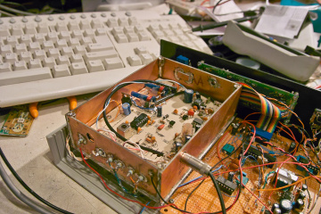
Top:  The main controller board for the Gunn controller.  The large chip is the PIC18F2620 microcontroller while the "daughter board" along the bottom contains a charge-pump converter to produce a 24 volt supply.  Also on that board is a standard audio transformer used to produce the 100 volt AC supply for the LCD's electroluminescent backlight.
Bottom:  A different view of the controller with the shield removed showing the modified Ramsey FR1C receiver used on the (tunable) 30 MHz IF.

Click on picture for a larger version.


As noted in the sidebar above, while I originally intended to use nonlinear equations for calculation the tuning voltage, it turned out that neither the compiler's built-in single-precision floating point or its 32-bit integer math was up to the task, so I chose the 3x3 matrix with the single-precision floating point and a straight-line approximation.  The straight-line approximation meant, however, that I could not vary too far from a given calibration frequency, so I decided to use several calibration points.

For example, the two common 10 GHz WFM operating frequencies, assuming a 30 MHz TX/RX split, are 10.250 GHz and 10.280 GHz.  For each of these two frequencies, I made the following measurements using a frequency counter to note the actual Gunn frequency with a counter as well as the LCD-displayed tuning voltage and Gunn temperature:
This gave several disparate points about the desired operating range and was repeated for each of the two 10 GHz frequencies - and I did this again on the two common 24 GHz frequencies for that unit, as well.  The procedure was quite simple:  Simply note the operating frequency with a counter along with the displayed temperature and tuning voltage, repeating this for a number of different frequencies at several different temperatures.

After selecting a reasonable spread of frequencies and temperatures, these voltages, frequencies and temperatures were plugged into the source code (as constants) in lieu of my getting around to finishing the code that was to read the 4k EEPROM.  I also wrote the code so that pushing the button on the rotary encoder would select one of four center frequencies - namely the two 10 GHz and the two 24 GHz standard WFM calling frequencies and the unit would crunch the 3x3 matrix, determine the coefficients, and then adjust the tuning voltage on the fly, based on my desired frequency and the actual Gunn temperature.

How well does it work?

Actually, it works pretty well!

The absolute frequency reading is accurate only to about 1 MHz or so on either 10 or 24 GHz and this is likely do to the fact that the Gunn oscillators that I am using do not contain ferrite isolators, so their frequency is "pulled" slightly by what is in front of their feedhorn - that is, free space or a dish:  Were I to use Gunn units with isolators, I would expect that the absolute frequency accuracy could be held to within a few hundred kHz or better.  Fortunately, these load-induced frequency offsets are more-or-less "constants" once the transceiver is set up and don't really enter into the "Voltage/Temperature versus Frequency" calculations!  Because of the straight-line approximation, the accuracy degrades rather rapidly once one gets more than 3 MHz or so off-frequency.

The temperature stabilization works quite well, too:  Over a +/-10C range, the Gunn frequency only moves by less than +/- 20kHz (on either 10 or 24 GHz) or so once the Gunn comes up to thermal equilibrium!  This degree of temperature stability is nearly enough to use narrowband FM without an AFC over that entire range, but practically speaking one probably could use narrowband FM and only have to occasionally tweak the tuning.  Since the slope of the temperature/voltage curve doesn't change very rapidly with frequency or temperature, the temperature stabilization is pretty good within a few MHz of the center frequency even if the calculated frequency display starts to become inaccurate.  If one tunes way off frequency (well away from the calibration points) the temperature compensation eventually starts to degrade, but it is still significantly better than it would be if it were un-compensated!

Were I able to have used the more-complicated nonlinear equations above, I suspect that I might achieve a bit better accuracy, but that would largely depend on the quality of the calibration points to begin with!  If/when I work on the code more, what I will probably do is not attempt to use the nonlinear equations, but allow a larger number of calibration points to be entered with the computer picking the three "nearest" ones to the current operating frequency and temperature and then proportionally "weighing" those that are "farther away".

It does take about 5 minutes or so for the Gunn to reach thermal equilibrium after power it up, but it is usable (e.g. not drifting too fast) after only a minute or so.

IF receiver:

Along with the computer control, I obtained a Ramsey FR-1C FM receiver and modified it for 30 MHz operation for use as an "IF" receiver.  This receiver and its modifications are described here:

    http://www.ka7oei.com/10gig/fr1c_mods.html


Comments and observations:

A
                  close-up view of the interior of the 24 GHz Gunn
                  module.
Figure 3:
A close-up view of the interior of the 24 GHz Gunn module.  The temperature sensor can be seen to be epoxied to the body of the Gunn oscillator while the 5 volt Gunn diode regulator and associated
components may be seen on the bottom of the case.  The small circuit board contains the components that couple modulation onto the Gunn's varactor tuning line.
Click on picture for a larger version.


When will it be completed?

Admittedly, I started and did most of the work on this project in 2003-2004, but in early 2005, I finally got my homebrew 10 GHz transverter operational to allow SSB and CW operation.  Since then, I've only rarely done WFM with the Gunn units and I've done almost no work on this device, so it sits around most of the time in a box, partially completed but "mostly" functional.

So, unless I get sudden inspiration or am sharply goaded into finishing this project and adding the features that I wanted, it may be a "while" before it's done!


Go to the KA7OEI microwave page.

or

Go to the KA7OEI main page.

This page last updated 20130322

Since 5/2011: